
Axial gap type motor

An axial gap and motor technology, applied in the field of winding technology, can solve problems such as price increases, and achieve the effect of improving winding workability

Inactive Publication Date: 2016-08-24
HITACHI AUTOMOTIVE SYST LTD
View PDF6 Cites 8 Cited by
  • Summary
  • Abstract
  • Description
  • Claims
  • Application Information

AI Technical Summary

Problems solved by technology

However, the prices of neodymium and dysprosium, which are raw materials for rare earth magnets, have risen sharply in recent years

Method used


Image

  • Axial gap type motor
  • Axial gap type motor
  • Axial gap type motor

Examples


Embodiment 1

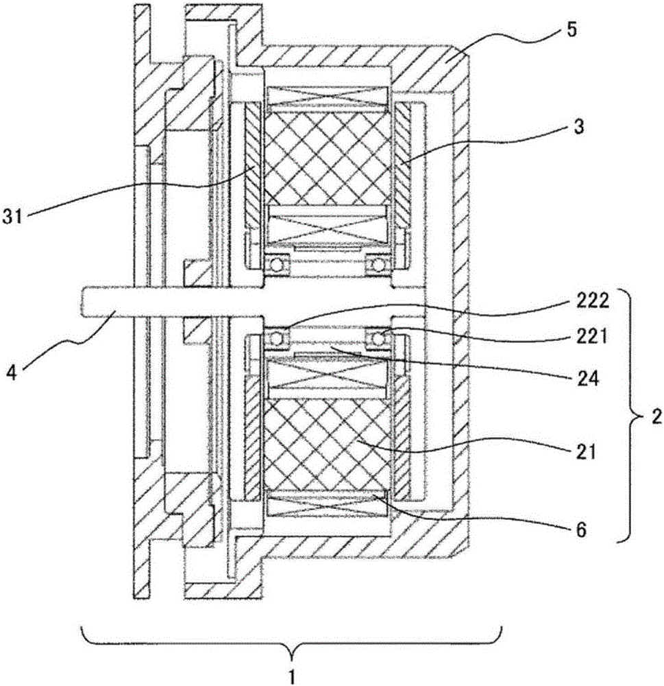
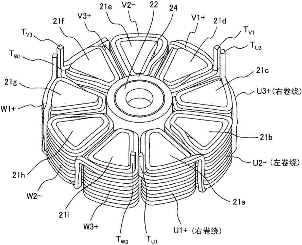
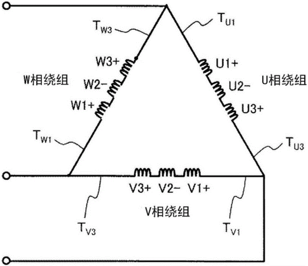
[0028] refer to Figures 1 to 4C , to illustrate the first embodiment of the present invention. figure 1 It is a sectional view of the axial gap motor 1 of this embodiment. figure 2 It is a perspective view of the stator 2 of this embodiment. image 3 is the wiring diagram of the stator winding of this embodiment. Fig. 4 is an explanatory diagram of the assembly procedure of the 1-phase coil of the present embodiment, Figure 4A is a graph showing its first order, Figure 4B is a diagram showing its second order, Figure 4C is a diagram showing its third order.

[0029] The axial gap motor 1 includes a flat cylindrical stator 2 and a pair of permanent magnet rotors 3 , 31 disposed opposite to each other with a predetermined gap on both axial surfaces of the stator 2 . The permanent magnet rotors 3 and 31 are fixed to an output shaft 4 that outputs a rotational driving force. In addition, the stator 2 and the permanent magnet rotors 3 and 31 are accommodated in the casi...

Embodiment 2

[0050] refer to Figure 5A , Figure 5B with Image 6 , to illustrate the second embodiment of the present invention. Figure 5A It is a schematic perspective view of the stator of this Example, and is a figure which shows the example which connected the coil in parallel. Figure 5B yes Figure 5A An enlarged view of the VB portion (wavy line portion) shown. Image 6 It is a connection diagram of the stator winding of this Example, and is a figure which shows the example which connected the coil in parallel.

[0051] In this embodiment, two sets of winding coils 6 are stacked in the direction of the rotation axis of the rotors 3 and 31 . exist figure 1 In the cross-sectional view of the axial gap motor, it is considered that the winding coil 6 configured in one stage (one layer) in the axial direction of the output shaft 4 may be configured in two stages (two layers).

[0052] In this example, if Figure 5A As shown, two sets of winding coils 6 are connected in paralle...


PUM


Abstract

The purpose of the present invention is to provide an axial gap type motor that can easily be assembled using a continuously wound coil as a stator coil of the axial gap type motor and that can improve winding workability by eliminating crossover lines on gap surfaces. Provided is an axial gap type motor that includes a stator and a rotor that face one another in the direction of the axis of rotation, the stator being configured so that a plurality of cores (21a-21i) and a plurality of winding coils (U1+-W3+) wound around the cores are disposed in the circumferential direction, wherein the first, second, and third winding coils (U1+, U2 , U3+) are respectively wound around the first, second, and third cores (21a-21c), which are arranged next to one another in this order in the circumferential direction, using a single continuous conducting wire, and the winding direction of the second winding coil (U2 ), which is wound around the second core (21b) located in the center, and the winding direction of the first and third winding coils (U1+, U3+), which are wound around the first and third cores (21a, 21c) located next to the second core (21b) on either side, are opposite.

Description

technical field [0001] The present invention relates to an axial gap motor, in particular to an axial gap motor configured such that the number of cores (slots) is a multiple of 9 for the slot combination of a rotor and a stator such as 8 poles and 9 cores (slots). For the appropriate winding technology. Background technique [0002] In recent years, global warming has become serious, and there has been an increasing demand for energy saving of electrical equipment. At present, about 55% of the domestic annual power consumption is consumed by motors, so there is a high degree of interest in improving the efficiency of motors. Conventionally, in order to increase the efficiency of motors, a design using a rare-earth magnet having a high energy product has been employed. However, the prices of neodymium and dysprosium, which are raw materials for rare earth magnets, have risen sharply in recent years. Therefore, an axial gap motor that can achieve high motor efficiency only...

Claims


Application Information

Patent Timeline
Patent Type & Authority Applications(China)
IPC IPC(8): H02K1/06H02K3/04H02K15/04H02K21/24
CPCH02K21/24H02K3/18H02K15/045H02K2213/03H02K1/182H02K1/2795H02K1/16
Inventor 川又昭一榎本裕治法月邦彦宝井健弥
Owner HITACHI AUTOMOTIVE SYST LTD
Learn More