
Micro cyclone separator with double-side air inlet function and high-pressure separation device adopting separator

A technology of cyclone separator and side air intake, which is applied in the direction of the device where the axis of the swirl can be reversed, the swirl device, etc., which can solve the problem of low rotational flow intensity of the medium, limited continuous operation time, low gas intake efficiency, etc. problems, achieve long-term safe operation, increase the intake area and medium processing capacity, and occupy a small area

Inactive Publication Date: 2016-08-31
BEIJING YUANCHENG IND SAFETY TECH CO LTD
View PDF9 Cites 10 Cited by
  • Summary
  • Abstract
  • Description
  • Claims
  • Application Information

AI Technical Summary

Problems solved by technology

Since this kind of micro cyclone separator has only one air inlet, the gas inlet efficiency is low, the medium rotation flow intensity is low, and there is a problem that the medium leaves directly from the top of the inner tube without separation, and there are low separation efficiency and low separation efficiency during use. The problem of excessive resistance loss
These problems of the miniature cyclone separator of the prior art have seriously affected its application in the gas-liquid or gas-solid-liquid separation device in the industrial field, causing the gas-liquid or gas-solid-liquid separation device to have an excessively large volume (large material consumption) , low separation efficiency, large resistance loss, large floor area, limited continuous operation time, etc.

Method used


Image

  • Micro cyclone separator with double-side air inlet function and high-pressure separation device adopting separator
  • Micro cyclone separator with double-side air inlet function and high-pressure separation device adopting separator
  • Micro cyclone separator with double-side air inlet function and high-pressure separation device adopting separator

Examples


Embodiment Construction

[0032] The present invention will be further explained below in combination with specific embodiments and accompanying drawings.

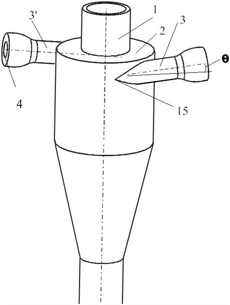
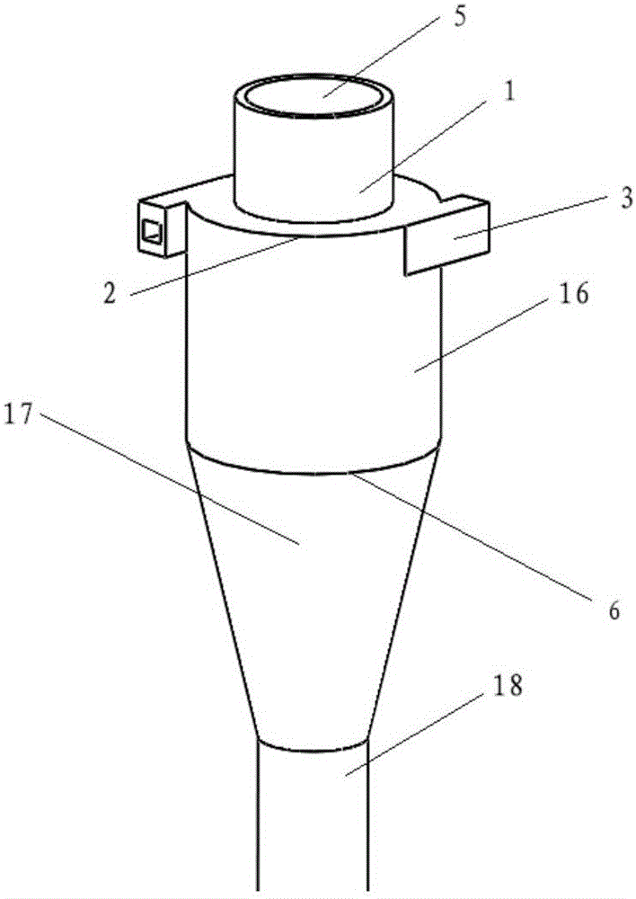
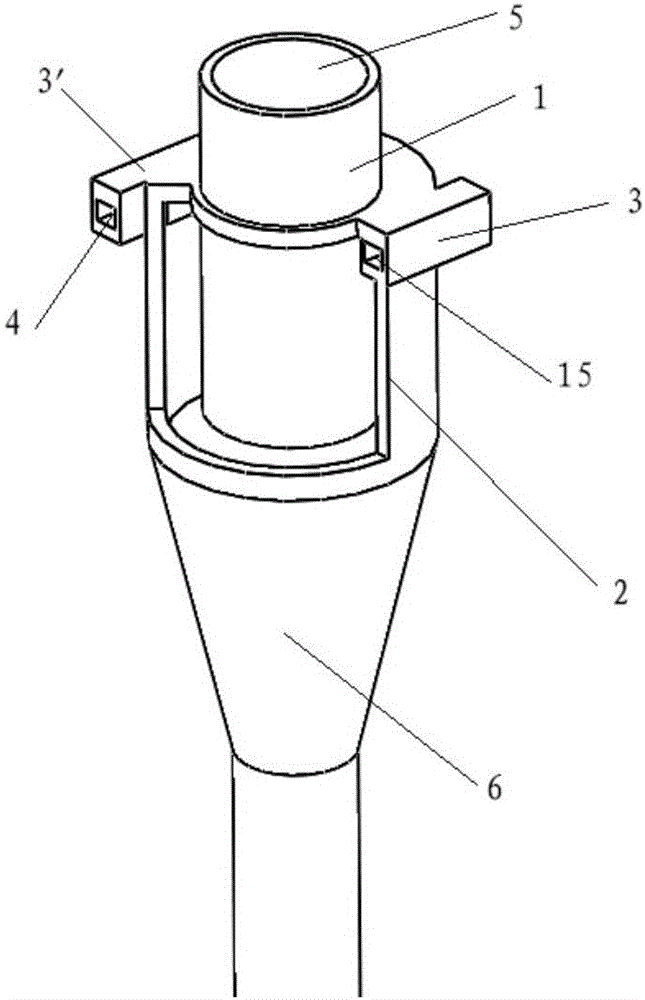
[0033] A kind of micro cyclone separator 6 of double-sided air intake of the embodiment of the present invention, as figure 1 and figure 2 As shown, it includes an inner tube 1 and an outer tube 2 , the inner tube 1 is a straight-through tube; the outer tube 2 includes an upper straight tube 16 , a middle tapered tube 17 and a lower straight tube 18 with a smaller diameter. The top of the inner pipe 1 is the gas outlet 5 of the cyclone separator, and a part of the lower part of the inner pipe 1 enters the upper straight pipe 16 of the outer pipe 2, and the top of the outer pipe 2 and the outer wall of the inner pipe 1 are closed and connected. The top of the outer wall of the outer tube 2 has two air inlets 3 and 3' communicating with the inside of the outer tube 2, and each air inlet 3 or 3' extends tangentially along the outer wall, and is symm...


PUM


Abstract

The invention provides a micro cyclone separator with a double-side air inlet function and a high-pressure separation device adopting the separator. The micro cyclone separator with the double-side air inlet function comprises an inner pipe and an outer pipe. An air outlet of the cyclone separator is formed in the top of the inner pipe. Part of the lower portion of the inner pipe enters the upper portion of the outer pipe. The top of the outer pipe is connected with the outer wall of the inner pipe in a sealing mode. The micro cyclone separator is characterized in that two air inlets communicating with the interior of the outer pipe are formed in the top of the outer wall of the outer pipe, and the two air inlets extend in the tangential direction of the outer wall of the outer pipe correspondingly and are distributed in a central symmetry mode. By means of the double-side air inlets which are distributed in the tangential direction in the central symmetry mode, the air inlet area is effectively increased, the air inlet efficiency is improved, the medium treating capacity is improved, the pressure drop is reduced, and the separation efficiency is improved.

Description

technical field [0001] The invention relates to the technical field of gas-liquid or gas-solid-liquid mixture separation, in particular to a double-sided air-intake micro-cyclone separator and a high-pressure separation device using the separator. Background technique [0002] The cyclone separator is a kind of equipment used for the separation of multi-phase systems. The working principle is to rely on the rotational movement of the airflow to make the solid particles or liquid droplets with large inertial centrifugal force thrown to the outer wall and separated. The cyclone separator usually includes an outer tube and an inner tube, a part of the lower part of the inner tube enters the upper part of the outer tube, the top of the inner tube is the gas outlet of the cyclone separator, and the top of the outer tube is sealed with the outer wall of the inner tube, and the outer tube includes the upper part The straight pipe part and the lower tapered pipe part; it can also in...

Claims


Application Information

Patent Timeline
Patent Type & Authority Applications(China)
IPC IPC(8): B04C5/04B04C5/28
CPCB04C5/04B04C5/28
Inventor 何伯述孙淑园段志鹏
Owner BEIJING YUANCHENG IND SAFETY TECH CO LTD
Learn More