Kitchen waste residue and liquid separator

A kitchen waste and separator technology, which is applied in the directions of liquid separation, filtration separation, separation methods, etc., can solve the problems of slow filtration, pollute the environment, and do not meet environmental protection regulations, and achieve the effect of separation.

Active Publication Date: 2016-08-31
重庆耐德生态科技有限公司
7 Cites 4 Cited by

AI-Extracted Technical Summary

Problems solved by technology

Although the filter tank of the device has achieved the effect of filtering and separating the oil in the food waste, the problems still exist in the device are: 1) the filter tank is only provided with a filter screen, so the food waste solid after separation still exists in the filter. 2) There is a filter screen fixed in the filter tank, after separation, the oil still exists in the filter tank, and the filter screen is in a static filtering state, which will not make the food waste solid Collision with warm water, so the filtration effect is not good, and the filtration speed is slow; 3) Since the solid food waste is a solid substance, its fluidity is far lower than that of fluid substances, so the single first solid slag conveyin...

Method used

As shown in Figure 1 to Figure 3, the present invention proposes a kind of food waste slag-liquid separator, comprising: frame 1; Steel pool body 2 installed on frame 1, to store warm water; A grate device 3 is arranged above the pool body 2 to store food waste solids; a lifting mechanism 4 is arranged on the frame 1, and the elevating mechanism 4 is connected with the grate device 3 so that the grate device 3 can be dipped or exposed back and forth. out of warm water; the frame 1 is provided with a drainage and slag scraping tank 5 next to the trough device 3, when the lifting mechanism 4 lifts the trough device 3 to a position flush with the draining slag trough 5, the trough device 3 Output the food waste solids to the drainage and slag scraping tank 5, which is used to discharge the food waste solids into the transport barrel; a slag-liquid separator 6 is provided at the bottom of the steel pool body 2 to separate the mixed slag The warm water and solid slag in the liquid are discharged separately; wherein, an oil port 21 is arranged on the top of the steel pool body 2 to discharge the oil when the oil surface overflows the oil port 21. In Fig. 1 and Fig. 2, there are two side-by-side food waste slag-liquid separators, which can be carried out simultaneously to speed up the separation speed and reduce the occupied area.
As shown in Figure 7, in order to design the scraper mechanism 52 that is simple in structure and easy to use, the scraper mechanism 52 includes: the slide rail 521 that is arranged on the top of the groove body 51 and the ball screw 522 that is arranged on the top of the body, the slide The rail 521 and the ball screw 522 are all parallel to the central axis of the tank body 51, and a scraper 523 is slidably connected to the slide rail 521, and the scraper 523 is screwed to the ball screw 522 through a ball screw nut 524; A motor 525 is installed outside, a first pu...

Abstract

The invention provides a kitchen waste residue and liquid separator. The kitchen waste residue and liquid separator comprises a rack, a steel tank body arranged on the rack to store warm water, a grate groove device arranged above the steel tank body to store solid kitchen waste, a lifting mechanism arranged on the rack and connected with the grate groove device to enable the grate groove device to be immersed in or emerge out of the warm water circularly, a water leaching and residue scratching groove formed beside the grate groove device and in the rack, and a residue and liquid separator body arranged at the bottom of the steel tank body to separably discharge the warm water and solid residues in the mixed residue and liquid. The kitchen waste residue and liquid separator has the beneficial effects that the kitchen waste is rapidly placed into the warm water and is rapidly transferred from the warm water, the solid kitchen waste transferred out of the warm water is rapidly discharged and continuously conveyed into a transporting barrel, and solid residues of small particles in the residue and liquid mixture are separated from the warm water.

Application Domain

Technology Topic

EngineeringWarm water +2

Image

  • Kitchen waste residue and liquid separator
  • Kitchen waste residue and liquid separator
  • Kitchen waste residue and liquid separator

Examples

  • Experimental program(1)

Example Embodiment

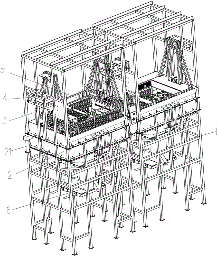
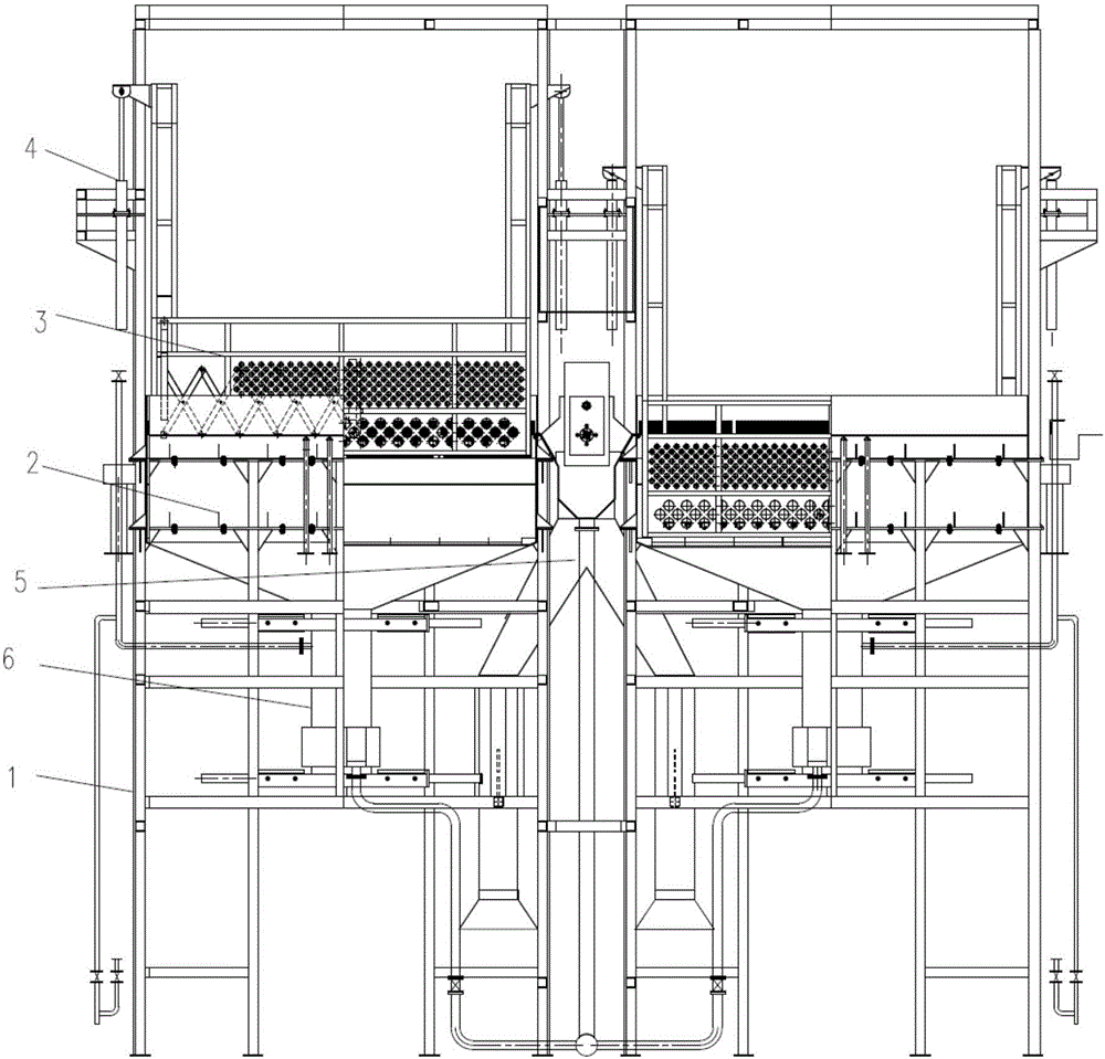
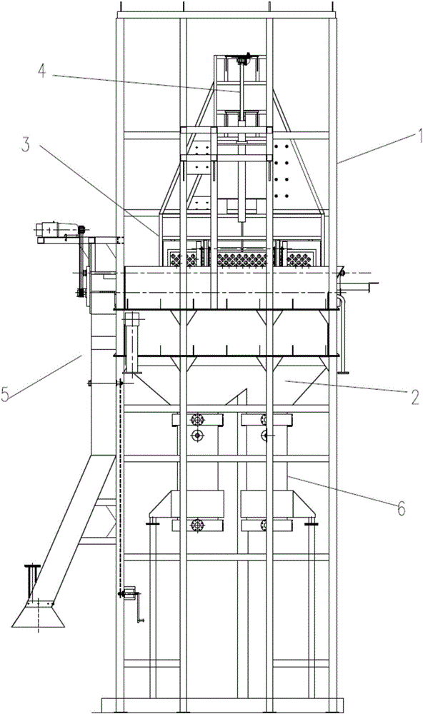
[0031] like Figure 1 to Figure 3 As shown, the present invention proposes a kitchen waste slag-liquid separator, comprising: a frame 1; a steel pool body 2 installed on the frame 1 to store warm water; a grate device is arranged above the steel pool body 2 3, to store food waste solids; on the frame 1, a lifting mechanism 4 is arranged, and the lifting mechanism 4 is connected with the trough device 3, so that the trough device 3 can be immersed in or out of warm water back and forth; on the frame 1 There is a draining and scraping tank 5 next to the draining device 3. When the lifting mechanism 4 lifts the draining device 3 to a position flush with the draining and scraping tank 5, the draining device 3 outputs food to the draining and scraping tank 5. Kitchen waste solids, draining and scraping slag tank 5 is used to discharge the food waste solids into the transport barrel; a slag-liquid separator 6 is arranged at the bottom of the steel pool body 2 to separate and discharge the warm water and solid slag in the mixed slag liquid ; Among them, the top of the steel pool body 2 is provided with an oil port 21 to discharge the oil when the oil surface overflows the oil port 21. figure 1 as well as figure 2 There are two side-by-side food waste slag-liquid separators in the middle, which can be carried out at the same time to speed up the separation speed and reduce the floor space.
[0032] like Figure 4 as well as Figure 5 As shown, in order to design a bi-grip device 3 with a loading function and a fast discharge of solid food waste, the grate device 3 includes: a filter tank 31 for carrying food waste, and the filter tank 31 is a cuboid structure with an open top , one side wall of the filter tank 31 is missing to form the outlet 311, the side wall of the filter tank 31 opposite to the outlet 311 is a movable plate 312, and the movable plate 312 can slide between adjacent two side walls; in the filter tank 31 The overcoat is provided with a frame 32 to be connected with the lifting mechanism 4; the movable plate 312 is connected with a shear mechanism 33 outside the filter tank 31 to promote the movable plate 312 to slide; and the first hydraulic cylinder 34 is installed on the frame 32, The first hydraulic cylinder 34 is connected with the shearing mechanism 33 to drive the expansion and contraction of the shearing mechanism 33; wherein, the end of the filter tank 31 provided with the discharge port 311 is used for sliding connection with the inner wall of the steel pool body 2, and separates the oil When separating the oil, the movable plate 312 is located at the end of the filter tank 31 opposite to the discharge port 311, and the movable plate 312 can slide to the discharge port of the filter tank 31 when the kitchen waste is discharged. The end where the outlet 311 is located. During work, at first, filter tank 31 is positioned at the top of steel pool body 2, and the sidewall of steel pool body 2 now seals the outlet 311 of filter tank 31, and the truck dumps kitchen waste into filter tank 31; then, start The lifting mechanism 4 of the food waste slag liquid separator makes the filter tank 31 loaded with food waste extend back and forth into the warm water prepared by the steel pool body 2, so that the warm water and the food waste solids impact each other back and forth, and the attached The oil on the solid food waste is washed out, thereby improving the filtration speed and filtering effect; afterward, when the oil is inserted back and forth into the steel pool body 2 for many times, the oil is basically separated, and the lifting mechanism 4 Raise the filter tank 31 to a position higher than the steel pool body 2 to expose the discharge port 311; finally, start the first hydraulic cylinder 34, so that the movable plate 312 slides from the initial position to the discharge port 311, and will be located in the filter tank 31 The food waste solid inside is discharged in the filter tank 31.
[0033] like Figure 5 as well as Image 6 Shown, in order to design the shearer mechanism 33 that takes up less space, the shearer mechanism 33 includes several root crossbars 331 and several link units; each link unit includes a middle bar 334 and two pairs of first Swing arm 332 and second swing arm 333, a pair of first swing arm 332 and second swing arm 333 are opposite to another pair of first swing arm 332 and second swing arm 333, a pair of first swing arm 332 and second swing arm 333 The middle part of the two swing arms 333 is hinged at one end of the middle cross bar 334, and the middle part of another pair of first swing arms 332 and the second swing arm 333 is hinged at the other end of the middle cross bar 334; The ends of a swing arm 332 and the second swing arm 333 are all hinged on the end of the side bar 331, and the first swing arm 332 upper end of each link unit is connected with the second swing arm of the adjacent link unit on one side. The upper end of 333 is jointly hinged on the end of one side cross bar 331, and the lower end of the first swing arm 332 is jointly hinged on the end of one side cross bar 331 with the lower end of the second swing arm 333 of the adjacent link unit on the other side; The side cross bar 331 of the connecting rod unit close to the first hydraulic cylinder 34 is connected with the piston rod of the first hydraulic cylinder 34; The piston rod 341 is connected; the movable plate 312 is provided with a vertical slide rail positioned in the vertical direction, and the cross bars 331 near the two sides of the movable plate 312 connecting rod unit are all slidably arranged in the vertical slide rail. During work, because the first hydraulic cylinder 34 is arranged on the top of the filter tank 31, the piston rod 341 of the first hydraulic cylinder 34 stretches out, and the side cross bar 331 will be pressed down, and the side cross bar 331 will move down to connect with it. The rotation of the first swing arm 332 or the second swing arm 333 drives the middle cross bar 334 to move forward, and the middle cross bar 334 makes all the first swing arms 332 and second swing arms 333 connected thereto move forward, and the first swing arm 332 And the second swing arm 333 extends forward, presses down the front edge cross bar 331, and the next link unit starts to extend forward, so that the entire shearing mechanism 33 is elongated, and the elongation of the shearing mechanism 33 makes the movable plate 312 slides from the initial position to the discharge port 311 to discharge solid food waste; in the same way, when the hydraulic cylinder retracts the piston rod 341, the first swing arm 332 and the second swing arm 333 are both deflected to the vertical direction, shearing and pushing The mechanism 33 is retracted, and the movable plate 312 returns to the initial position, waiting for the next separation work to be carried out.
[0034] Please continue to refer Figure 4 As shown, in order to make the connection between the frame 32 and the lifting mechanism 4 of the food waste slag-liquid separator stable and the strength of the suspension frame too rigid, the frame 32 includes a frame body 321 in which the filter tank 31 is framed, and the two ends of the frame body 321 All are provided with the suspension frame that is used to be connected with lifting mechanism 4, and suspension frame comprises center frame 322 and four reinforcement rods 323, and four reinforcement rods 323 are evenly and symmetrically installed on two opposite sides of center frame 322, and each reinforcement One end of the rods 323 is connected to the side of the center frame 322 , and the other end of each reinforcing rod 323 is connected to the frame 32 , and the top of the center frame 322 is provided with a mounting plate 324 for being installed on the lifting mechanism 4 . Since the food waste plus the weight of the entire grate device 3 is 3 to 8 tons, the strength and stability of the suspension frame are required to be high.
[0035] like Figure 7 as well as Figure 8 As shown, in order to realize the selective communication between the main drop pipe and one of the sub-feeding pipes, realize the alternate use of the two sub-feeding pipes to input food waste solids into the transport barrel, and the food waste solids will not be discharged during the alternate process. The output of food waste solids will be interrupted, and the drainage and slag scraping tank 5 includes: a tank body 51 located above the steel pool body 2 and next to the grate device 3, to receive the food waste solids discharged from the discharge port 311 of the grate device 3; The scraping mechanism 52 arranged on the tank body 51 is used to scrape out the solid food waste in the tank body 51; the main blanking pipe 53 connected with one end of the tank body 51; pipe 54; and a pipeline switching mechanism 55 arranged at the connection between the two sub-feeding pipes 54 and the main dosing pipe 53, so as to selectively connect the main dosing pipe 53 with one of the dotting pipes 54.
[0036] like Figure 7 As shown, in order to design a scraper mechanism 52 with simple structure and easy use, the scraper mechanism 52 includes: a slide rail 521 arranged on the top of the tank body 51 and a ball screw 522 arranged on the top of the body, the slide rail 521 and the ball screw 522 are all parallel to the central axis of the tank body 51, and a scraper 523 is slidably connected on the slide rail 521, and the scraper 523 is threadedly connected with the ball screw 522 through a ball screw nut 524; a motor 525 is installed outside the tank body 51, The rotating shaft of the motor 525 is connected with a first pulley 526, and the end of the ball screw 522 close to the motor 525 is connected with a second pulley 527, and the first pulley 526 and the second pulley 527 are connected by a belt 528 to Drive the ball screw 522 to rotate. First, the food waste solids are transferred into the tank body 51; then, the motor 525 is started, and the motor 525 drives the first pulley 526 to rotate, and the rotation of the first pulley 526 drives the rotation of the second pulley 527 through the belt 528 at the same time. The rotation of the second pulley 527 makes the ball screw 522 rotate, and the rotation of the ball screw 522 makes the scraper 523 threaded with it move from one end of the tank body 51 to the other end (that is: the tank body 51 and the main discharge tube 53 The end of the connection), the slide rail 521 guides the movement of the scraper 523 to prevent the scraper 523 from being worn due to deviation, and scrapes all the food waste solids in the tank body 51 under the action of the scraper 523 into the main drop tube 53, and then fall into a branch drop tube 54 in the open state (the other point drop tube 54 is in the closed state), and fall into the branch drop tube 54 in the open state. In the transport bucket just below; Finally, when the transport barrel is full, use the pipeline switching structure so that the sub-feeding tube 54 that was originally in the open state is closed, and the sub-feeding tube 54 that is in the closed state is opened. The solid food waste falls into the newly opened transport barrel, which realizes the continuous discharge of the solid food waste, improves the speed of discharging the solid food waste, and prevents the solid food waste from falling to the ground.
[0037] like Figure 7 as well as Figure 8 As shown, in order to design a pipeline switching mechanism 55 with a simple structure and easy use, the pipeline switching mechanism 55 includes: a transmission shaft 551 installed in the middle of the connection between the two drop pipes 54, and a turning plate 552 is connected to the transmission shaft 551 , the drive shaft 551 extends out of the two-point drop pipe 54 and the outer end of the main drop pipe 53 is connected with a sprocket 553, and the sprocket 553 is connected with an L-shaped power shaft 555 through a transmission chain 554, and the free end of the power shaft 555 is connected There is a rocker arm 556. Since the connection between the two-point drop tube 54 and the main drop tube 53 is generally at a higher position, by setting this structure, it is only necessary to turn the hand rocker arm 556 at a lower position to make the power shaft 555 rotate, and the power shaft 555 drives the sprocket 553 to rotate through the transmission chain 554, thereby driving the flap 552 to rotate by driving the transmission shaft 551. When the flap 552 rotates to the entrance of a sub-feeding pipe 54, the sub-feeding pipe 54 is in a closed state , then another sub-feeding pipe 54 conduction.
[0038] The outlet of the sub-blanket 54 is provided with a suction pipe to suck away the foul smell produced by the kitchen waste to prevent air pollution.
[0039] like Figure 9 As shown, in order to realize the discharge of warm water after the oil-liquid separation, and realize the removal of the separated solid slag from the grate bucket grid, the slag-liquid separator 6 includes: a separation pipe 61 connected to the bottom of the steel pool body 1 , the end of the separation pipe 61 connected to the container is the inlet end, the other end of the separation pipe 61 is the outlet end, and the outer wall of the separation pipe 61 near the outlet end is provided with a water outlet 611; the first flashboard installed on the end face of the separation pipe 61 inlet Valve 62; The second gate valve 63 installed on the end face of the separation pipe 61 outlet end; And the grate bucket grid (not shown) installed between the first gate valve 62 and the second gate valve 63, And the grate bucket grid is arranged in the separation pipe 61; wherein, the grate bucket grid is a closed fence structure, and the first gate valve 62 and the second gate valve 63 are used to open and close the two ends of the grate bucket grid respectively; There is a gap between the bucket grill and the inner wall of the separation pipe 61 .
[0040] like Figure 10 as well as Figure 11As shown, in order to design the first gate valve 62 and the second gate valve 63 with simple structure and convenient use and installation, both the first gate valve 62 and the second gate valve 63 include The valve cavity body 621 on the end face, the valve cavity body 621 is a frame structure, the center of the valve cavity body 621 is the discharge port 622, and two sealing cavities 623 are respectively installed on the two opposite sides of the valve cavity body 621; A second hydraulic cylinder 624 is installed on the side of the body 623 away from the valve cavity 621, and the piston rods of the second hydraulic cylinder 624 extend into the respective sealed cavity 623, and the two piston rods 341 are connected with a gate 625, the flashboard 625 passes through the valve cavity 621 after passing through the sealing cavity 623; wherein, when the two flashboards 625 are in a closed state, the two flashboards 625 close the discharge port 622; when the two flashboards 625 are in a separated state , the two flashboards 625 open the discharge port 622. When working, firstly, the first gate valve 62 is opened, the two hydraulic cylinders of the first gate valve 62 are activated, and the piston rod is retracted, so that the gate plate 625 originally in a closed state is separated, and the first gate valve 62 is opened. , now the second gate valve 63 is in the closed state (that is: the two gates 625 of the second gate valve 63 are in the closed state), at this time the slag-liquid mixture enters the grate bucket grid from the first gate valve 62 , water flows into the gap between the grate bucket grid and the separation pipe 61 from the side wall of the grate bucket grid, and finally is discharged into the water receiving device through the water outlet 611 and the water outlet pipe. It cannot pass through the grate bucket grid, and is deposited in the grate bucket grid; then, when the solid slag can be seen through the observation port, close the first gate valve 62, open the second gate valve 63, and the solid slag will pass through the grate bucket grid. drain from the bottom of the grid.
[0041] The working principle of this embodiment: when working, at first, the train for transporting food waste will dump all the food waste into the filter tank 31 of the grate device 3; then, start the lifting mechanism 4, so that all the food waste in the filter tank 31 The kitchen waste extends back and forth into the warm water of the steel pool body 2, and the separated oil floats on the warm water surface. Body 2 is discharged to realize the separation of oil and liquid; after that, after being inserted into warm water several times back and forth, the oil attached to the solid food waste is basically separated. At this time, the lifting mechanism 4 needs to be started again to make the grate The discharge port 311 of 3 is flush with the feed port of draining and scraping slag tank 5; then, start the first hydraulic cylinder 34 of grate device 3, and act on movable plate 312 by shearing and pushing mechanism 33, and all the filter tanks in filter tank 31 The food waste solids are discharged into the tank body 51 of the drainage and slag scraping tank 5; then, the motor 525 of the drainage and slag scraping tank 5 is started, so that the food waste solids are discharged into an opened drop pipe, and then discharged to the transportation When the drop pipe is full, the management switching mechanism is used to open the other drop pipe (the drop pipe is closed), and the solid food waste falls into the pre-prepared empty transport barrel through another drop pipe In the process, the continuous discharge of food waste solids is realized; finally, after the oil is discharged from the oil outlet 311, warm water needs to be replaced, because more or less small particles of solid residue pass through the filter tank during the oil-liquid separation process If the gap in 31 enters the warm water, solid slag and warm water need to be separated during discharge. Use the slag-liquid separator 6 to open the first gate valve 62 and close the second gate valve 63 to separate the warm water first, and then Close the first gate valve 62, open the second gate valve 63, and discharge the solid slag in the grating bucket grid.

PUM

no PUM

Description & Claims & Application Information

We can also present the details of the Description, Claims and Application information to help users get a comprehensive understanding of the technical details of the patent, such as background art, summary of invention, brief description of drawings, description of embodiments, and other original content. On the other hand, users can also determine the specific scope of protection of the technology through the list of claims; as well as understand the changes in the life cycle of the technology with the presentation of the patent timeline. Login to view more.

Similar technology patents

Classification and recommendation of technical efficacy words

Why Eureka
Try Eureka