Material charging box for bonding of neodymium iron boron magnet

A neodymium-iron-boron and charging box technology is applied to the material box for NdFeB magnet bonding and the field of neodymium-iron-boron magnets, which can solve the problem that the sealing effect of the material box is not very good, affecting the performance of the neodymium-iron-boron magnet, etc. problems, to achieve the effect of preventing gaps, improving performance, and improving sealing performance

Inactive Publication Date: 2016-08-31
成都德兴磁业有限公司
View PDF1 Cites 6 Cited by
  • Summary
  • Abstract
  • Description
  • Claims
  • Application Information

AI Technical Summary

Problems solved by technology

[0005] Since the material box is in use, the material box cover is set on the material box body, during the transportation of the NdFeB green body, there is a gap between the material box cover and the material box body due to the vibration, resulting in the use of The sealing effect of the material box is not very good, which will eventually affect the performance of the NdFeB magnet

Method used


Image

  • Material charging box for bonding of neodymium iron boron magnet
  • Material charging box for bonding of neodymium iron boron magnet
  • Material charging box for bonding of neodymium iron boron magnet

Examples


Embodiment 1

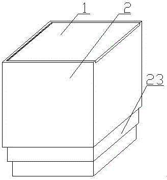
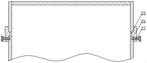
[0032] A charging box for bonding NdFeB magnets, comprising a material box body 2, a connecting shaft 3, and a material box cover 1, the side wall of the material box body 2 is provided with a communication channel with the inside of the material box body 2 Stoma 25, described air hole 25 is equipped with plug 26, is connected with guide rod 27 on the described plug 26, and described guide rod 27 passes through the guide hole on the plug 26 and meets the side of material box body 2 Wall connection; the top of the connecting side wall of the material box body 2 is provided with a mounting groove 21, and the connecting end of the material box cover 1 is located in the mounting groove 21 of the material box body 2, and the cylindrical surface of the material box cover 1 17 fits with the arc surface 22 of the material box body 2; a partition plate 15 is arranged in the described material box cover 1, and the inner cavity of the material box cover 1 is divided into a left chamber 16...

Embodiment 2

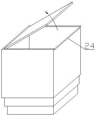
[0034] On the basis of Embodiment 1, the top surface of the connecting opposite surface 24 of the magazine body 2 is lower than the remaining sides of the magazine body 2, and the top surfaces of the remaining sides of the magazine body 2 are even, and the magazine The height difference between the top surface of the connecting opposite surface 24 of the body 2 and the top surface of the remaining sides of the cartridge body 2 is equal to the thickness of the cartridge cover 1 .

Embodiment 3

[0036] On the basis of the first or second embodiment, at least two steps 23 are arranged at the bottom of the cartridge body 2 .


PUM


Abstract

The invention discloses a material charging box for bonding of a neodymium iron boron magnet, belongs to a material utilizing box for bonding of the neodymium iron boron magnet in the technical field of magnets and aims at providing the material charging box for bonding of the neodymium iron boron magnet. The material charging box comprises a material box body, a connecting shaft and a material box cover. Ventilation holes are formed in the side wall of the material box body and provided with plugs. The plugs are connected with guide rods. The guide rods are connected with the side wall of the material box body. The cylindrical face of the material box cover is attached to the arc face of the material box body. A partition plate is arranged in the material box cover and divides an inner cavity of the material box cover into a left cavity and a right cavity. The two ends of the connecting shaft penetrate the left cavity of the material box cover and then are connected with the material box body. A compression spring and a fixing base are arranged in the right cavity. One end of the compression spring is pressed on the partition plate, and the other end of the compression spring is connected with the fixing base. The fixing base is connected with an elastic rope, the other end of the elastic rope sequentially penetrates the compression spring and the partition plate and then is connected to the connecting shaft in a winding manner, and the tail end of the elastic rope and the connecting shaft are fixedly connected.

Description

technical field [0001] The invention belongs to the technical field of magnets, and relates to a neodymium-iron-boron magnet, in particular to a material box for bonding neodymium-iron-boron magnets. Background technique [0002] NdFeB magnets are permanent magnets with the strongest magnetic force so far, which are divided into bonded NdFeB magnets and sintered NdFeB magnets. Bonded NdFeB is actually injection molding, and sintered NdFeB is vacuumized and heated at high temperature. [0003] Whether it is bonded NdFeB or sintered NdFeB, a material box is usually used, and the NdFeB green body is placed in the material box, and then the cover of the material box is covered, and the material box and the NdFeB in the material box The boron green body is transported to the sintering furnace for sintering or transported to the designated position for bonding. But, the known material box overwhelming majority in the prior art comprises material box body and the material box cov...

Claims


Application Information

Patent Timeline
Patent Type & Authority Applications(China)
IPC IPC(8): B65D43/16B65D43/26B65D1/22B65D1/40
CPCB65D43/166B65D1/22B65D1/40B65D43/26B65D2205/02
Inventor 徐霞付磊
Owner 成都德兴磁业有限公司
Why Eureka
Try Eureka