Battery loading and unloading system with tray, and method thereof
A pallet and battery technology, applied in the direction of conveyor objects, transportation and packaging, etc., can solve the problems of poor contact between tabs and machine circuit layers, production efficiency, low utilization rate of machine body, poor anti-pollution ability, etc., to solve poor contact Problems, improve machine operation efficiency, and strong anti-pollution ability
- Summary
- Abstract
- Description
- Claims
- Application Information
AI Technical Summary
Problems solved by technology
Method used
Image
Examples
Embodiment 1
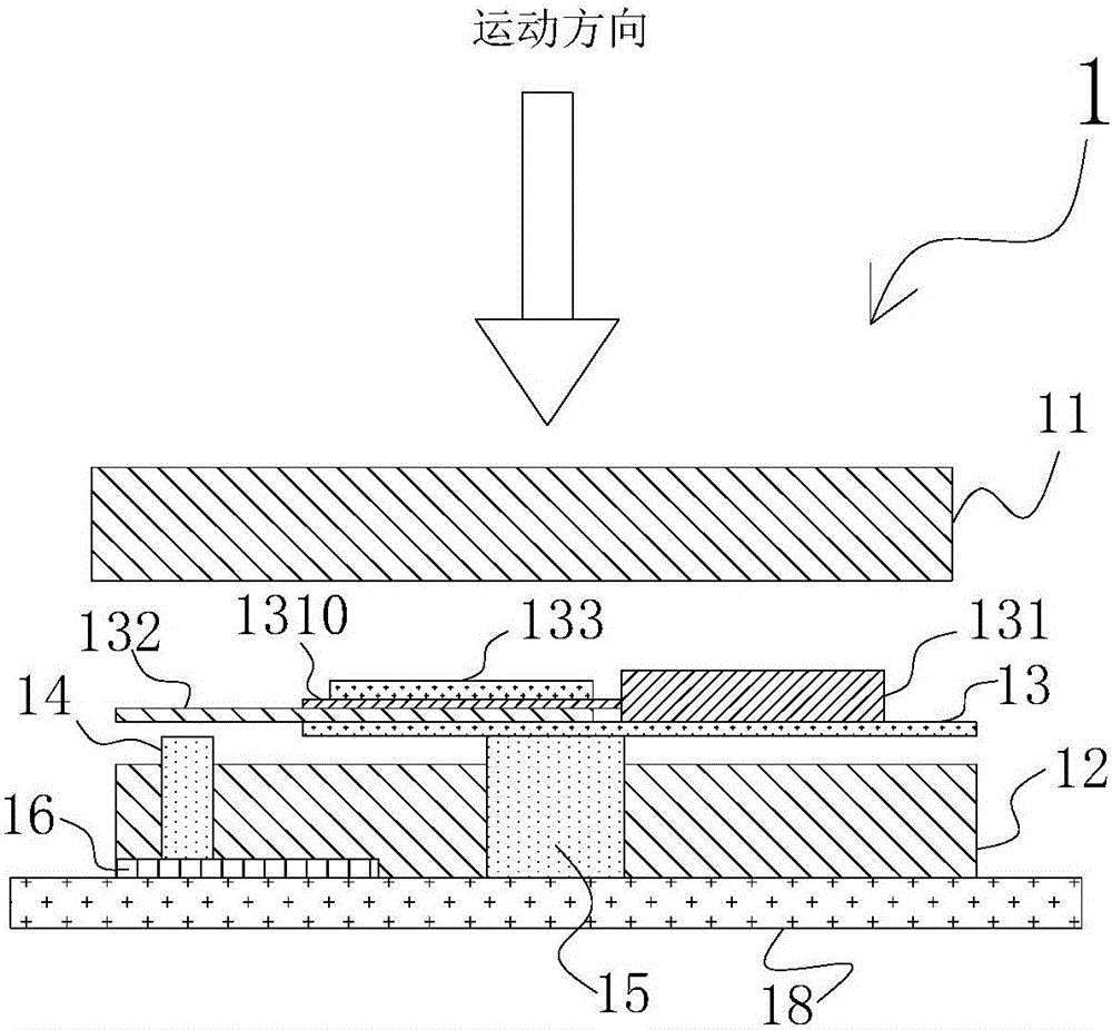
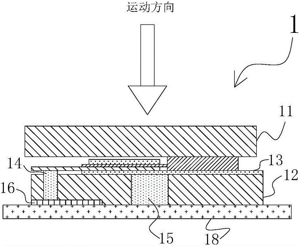
[0038] Such as Figure 1~2 as shown, figure 1 It is a diagram of the electrical connection state before pressing the battery on the pressing plate of the upper machine, figure 2 The electrical connection state diagram after pressing the battery for the upper machine pressing plate. A battery loading and unloading system with a tray described in the embodiment of the present invention, such as figure 1 As shown, the machine body 1 is included, and the machine body 1 is provided with a machine pressing plate. The machine pressing plate includes an upper machine pressing plate 11 and a lower machine pressing plate 12. The lower machine pressing plate 12 is provided with an elastic conductive device 14 and an elastic supporting device 15. The elastic conductive The device 14 is connected with the circuit layer 16 of the machine press plate; the battery tray 13 for containing the battery 131 can be placed on the elastic support device 15;
[0039] The battery tray 13 is provide...
Embodiment 2
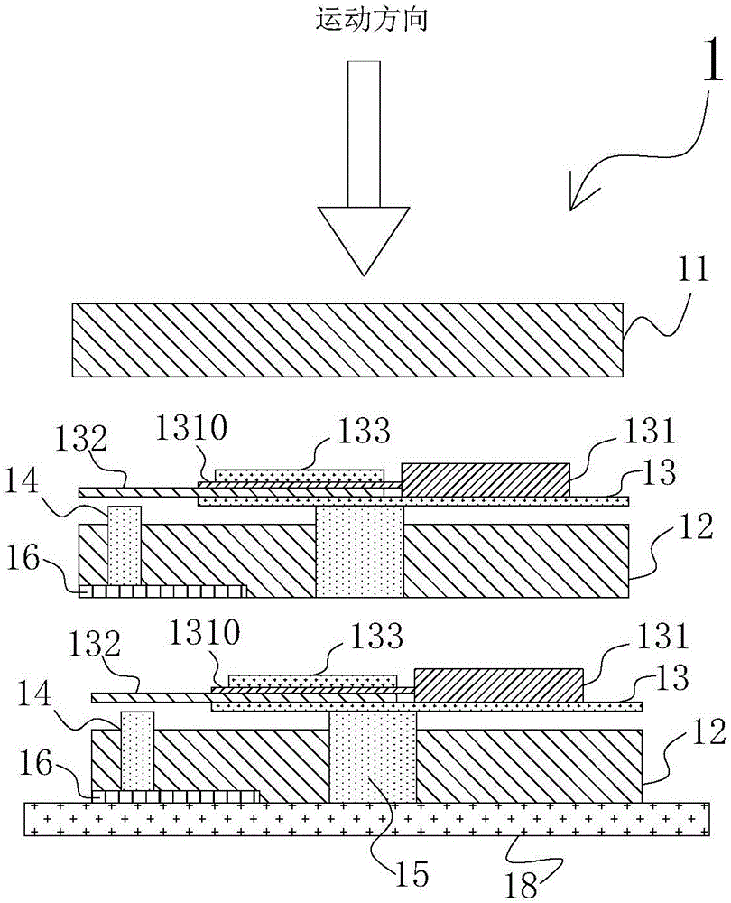
[0053] Such as Figure 3-4 as shown, image 3 It is the diagram of the electrical connection state before the pressing plate of the upper machine presses the battery, Figure 4 The electrical connection state diagram after pressing the battery for the upper machine pressing plate. Different from Embodiment 1, several layers of lower machine pressing plates 12 can be arranged in the machine body 1 in this embodiment, and a battery tray 13 can be placed on each lower machine pressing plate, that is, multiple layers of batteries are placed in the machine body 1. The tray 13 can charge and discharge multiple batteries 131 at a time. The specific number of layers can be determined according to the actual situation.
Embodiment 3
[0055] Refer below Figure 1-4 The battery loading and unloading method of the battery loading and unloading system with trays of the present invention is described.
[0056] When loading, place the battery on the battery tray outside the machine body, clamp the tabs on the battery between the tray circuit layer and the tab clamping device, and position the battery at the same time, the tray circuit layer and the battery pole ear conduction; then place the battery tray on the elastic support device in the machine body; at this time, the tray circuit layer is above the elastic conductive device and is not in contact with the upper end surface of the elastic conductive device;
[0057] When the top machine pressure plate starts to close, the upper machine pressure plate presses the battery and drives the battery tray to press down, so that the elastic support device on the lower machine pressure plate is compressed, and the tray circuit layer is also in contact with the elastic ...
PUM
 Abstract
Description
Claims
Application Information
 - R&D
- Intellectual Property
- Life Sciences
- Materials
- Tech Scout
- Unparalleled Data Quality
- Higher Quality Content
- 60% Fewer Hallucinations
Browse by: Latest US Patents, China's latest patents, Technical Efficacy Thesaurus, Application Domain, Technology Topic, Popular Technical Reports.
© 2025 PatSnap. All rights reserved.Legal|Privacy policy|Modern Slavery Act Transparency Statement|Sitemap|About US| Contact US: help@patsnap.com


