Method for changing stroke of double-well pumping unit

A pumping unit and stroke technology, which is applied in the direction of earthwork drilling, wellbore/well parts, production fluid, etc., can solve the problems of heavy drum weight, time-consuming and labor-intensive disassembly, etc., and achieve reduced labor intensity, low cost, and durability. good grinding effect

Active Publication Date: 2016-08-31
BC P INC CHINA NAT PETROLEUM CORP +2
View PDF7 Cites 1 Cited by
  • Summary
  • Abstract
  • Description
  • Claims
  • Application Information

AI Technical Summary

Problems solved by technology

The whole process took 3 days (including cleaning up the site), and the cost was about 40,000 yuan (including 7,000 yuan for the oil well pump); the oil production affected by the shutdown was calculated as 60 tons, and the user lost 48,000 yuan
The total cost and economic loss brought to the user by replacing the oil well pump is 88,000 yuan
[0007] The second method of replacing one of the drums in the double well pumping unit requires the supplier of the double well pumping unit to equip the drums with different outer diameters, which is costly
Due to the heavy weight of the drum, the minimum weight of the drum is 600 kg. It i

Method used


Image

  • Method for changing stroke of double-well pumping unit

Examples


Embodiment 1

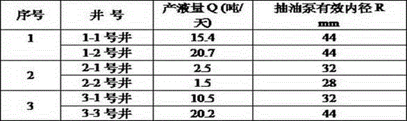
[0035] Example 1: The first double well pumping unit

[0036] 1. The stroke ratio of No. 1-1 well and No. 1-2 well

[0037] i = (Q 1 × R 2 2 ) / (Q 2 × R 1 2 )=15.4×(44 / 2) 2 / 20.7×(44 / 2) 2 =0.74

[0038] That is, A1 / A2=0.74 (A1 is the stroke of No. 1-1 oil well, A2 is the stroke of No. 1-2 oil well)

[0039] i < 0.95, indicating that the outer diameter of the drum corresponding to the No. 1 oil well is smaller than that of the No. 2 oil well, and a bushing should be added to the No. 2 drum.

[0040] 2. The thickness of the bushing

[0041] d=(1-i)×∮ / 2

[0042] d=(1-0.74)×600 / 2

[0043] =78(mm)

[0044] The outer diameter of the added bushing: 600+78×2=756 (mm)

Embodiment 2

[0045] Embodiment 2: The second double well pumping unit

[0046] 1. The stroke ratio of No. 2-1 well and No. 2-2 well

[0047] i = (Q 1 × R 2 2 ) / (Q 2 × R 1 2 )=2.5×(28 / 2) 2 / 1.5×(32 / 2) 2 =1.28

[0048] That is, A1 / A2=1.28

[0049] i>1.05, indicating that the outer diameter of the drum corresponding to the No. 1 oil well is larger than that of the No. 2 oil well, and a bushing should be added on the No. 1 drum.

[0050] 2. The thickness of the bushing

[0051] d=(i-1)×∮ / 2 =(1.28-1)×600 / 2=84(mm)

[0052] The outer diameter of the additional bushing: 600+84×2=768 (mm)

Embodiment 3

[0053] Embodiment 3: The third double well pumping unit

[0054] 1. The stroke ratio of No. 3-1 well and No. 3-2 well

[0055] i = (Q 1 × R 2 2 ) / (Q 2 × R 1 2 ) =10.5×(44 / 2) 2 / 20.2×(32 / 2)2 =0.98

[0056] 0.95≦i≦1.05, indicating that the drum corresponding to the No. 1 oil well and the drum corresponding to the No. 2 oil well do not need to add bushings.


PUM


Abstract

The invention discloses a method for changing the stroke of a double-well pumping unit, and solves the problems of high cost, low efficiency and the like of the existing method for regulating the stroke of the double-well pumping unit. The method concretely comprises the following steps that the stroke ratio of two wells is calculated according to the liquid yield of the two wells and the effective inner diameter of an oil pump; then, a bushing needs to be additionally arranged on a rolling tube of which well is judged according to the ratio, wherein the length, the inner diameter, the spiral groove type and the rotation direction of the bushing are consistent with the rolling tube; the thickness of the bushing is obtained according to a formula of d=(i-1)*phi/2; and the bushing is cut into two halves along the center line, and is then fixed on the corresponding rolling tube. The method provided by the invention has the advantages that the theory that the stroke is in direct proportion to the diameter of the driving rolling tube is used as the basis; after the additional arrangement of the bushing, the operation lengths of the steel wire ropes wound on the driving rolling tube are different; the stroke regulation is finally realized; the weight of the bushing is light, so that the mounting and the dismounting are convenient; and the stroke regulating cost and the work intensity of workers are greatly reduced.

Description

technical field [0001] The invention relates to a method for changing the stroke of a double well pumping unit. Background technique [0002] The double-well pumping unit pumps two oil wells at the same time with one pumping unit, that is, when the sucker rod of one oil well goes up, the sucker rod of the other oil well goes down; the upper and lower loads of the two oil wells are alternately changed to achieve mutual balance. [0003] The power transmission system of the double well pumping unit is composed of a motor, a reducer, and a drum A and a drum B connected in series on the same transmission shaft. Two steel wire ropes are wound on the drum A and the drum B respectively. When working, the control system controls the positive and negative rotation of the motor, driving the No. 1 well drum A and the No. 2 well drum B on the transmission shaft to rotate; the steel wire rope wound on the drum to transmit power uses the guide wheel to drive the sucker rods of the two oil...

Claims


Application Information

Patent Timeline
IPC IPC(8): E21B43/12
CPCE21B43/121
Inventor 彭章建刑延方宛立达王德威李金民王庆喜郝军才
Owner BC P INC CHINA NAT PETROLEUM CORP
Why Eureka
Try Eureka