Compression condensation system with ejector

An ejector and condenser technology, applied in the field of physics, can solve the problems of long operation time, large condensation load, complicated operation, etc., and achieve the effect of short operation time, less condensation load, and reduced condensation load

Inactive Publication Date: 2016-08-31
UNIV OF SHANGHAI FOR SCI & TECH
View PDF7 Cites 7 Cited by
  • Summary
  • Abstract
  • Description
  • Claims
  • Application Information

AI Technical Summary

Problems solved by technology

[0008] Aiming at the above-mentioned technical problems in the prior art, the present invention provides a compression condensing system with an ejector. The compression condensing system with an ejector should

Method used


Image

  • Compression condensation system with ejector
  • Compression condensation system with ejector
  • Compression condensation system with ejector

Examples


Example Embodiment

[0022] Example 1

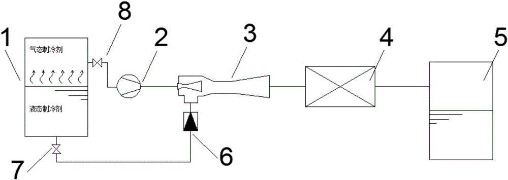
[0023] Such as figure 1 As shown, the present invention provides a refrigerant recovery system with an ejector, including a recovered container 1, a refrigeration compressor 2, an ejector 3, a condenser 4, and a recovery container 5. The recovered container 1 and a first Two shut-off valves 8 are connected, the second shut-off valve 8 is connected with the refrigeration compressor 2, the refrigeration compressor 2 is connected with the ejector 3, and the ejector 3 is connected with the The condenser 4 is connected, the condenser 4 is connected to the recovery container 5, the ejector 3 is also connected to a one-way valve 6, and the one-way valve 6 is connected to a first stop valve 7 , The first shut-off valve 7 is connected to the recovered container 1.

[0024] When there is liquid refrigerant in the recovered container 1, such as figure 1 As shown, valves 7 and 8 are open, the suction pipe of the refrigeration compressor 2 is connected to the gas pipe of th...

Example Embodiment

[0028] Example 2

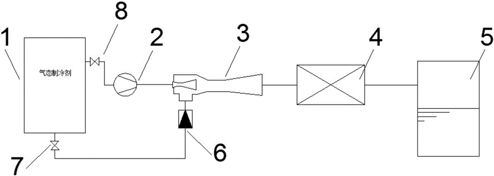
[0029] When there is only refrigerant wet vapor or dry vapor in the recovered container 1, such as figure 2 Shown.

[0030] The connection mode and operating principle of the system are the same as those of the first embodiment. The difference is that the substance injected by the ejector 3 is a gaseous refrigerant at this time.

[0031] Although the ejector 3 no longer injects liquid refrigerant, the exhaust from the compressor 2 injects the gaseous refrigerant in the recovered container 1. The injected refrigerant does not need to be compressed into a high temperature and high pressure state by the compressor 2, which can be compared with the embodiment 1 The same beneficial effect.

Example Embodiment

[0032] Example 3

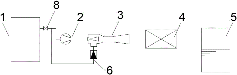
[0033] Such as image 3 As shown, the present invention also provides another refrigerant recovery system with ejector, including the recovered container 1, the refrigeration compressor 2, the ejector 3, the condenser 4, and the recovery container 5. The recovered container 1 and A second stop valve 8 is connected, the second stop valve 8 is connected to the refrigeration compressor 2, the refrigeration compressor 2 is connected to the ejector 3, and the ejector 3 is connected to the The condenser 4 is connected, the condenser 4 is connected with the recovery container 5, the ejector 3 is also connected with a one-way valve 6, and the one-way valve 6 is connected to the second shut-off valve 8. The pipeline communicates with the refrigeration compressor 2.

[0034] When the recovered container 1 does not have a liquid pipe, or it is inconvenient for liquid recovery, the ejector 3’s ejector inlet is connected in parallel with the refrigeration compressor 2 sucti...


PUM


Abstract

The invention provides a compression condensation system with an ejector. The compression condensation system comprises a recycled container, a refrigeration compressor, the ejector, a condenser and a recycling container. When the compression condensation system is used for a refrigerant recycling system, compressor exhaust drives an ejected refrigerant to enter the condenser together through the ejector, not all liquid refrigerants need to be completely evaporated into gas refrigerants which enter the compressor to be compressed, and temperature rise and pressure rise are avoided, so that condensation loads are few; the gas refrigerants and the liquid refrigerants are recycled at the same time, the running time is short, and the service life of the compressor is prolonged. The invention further provides a refrigeration system with an ejector. The refrigeration system comprises a gas-liquid separator, a refrigeration compressor, the ejector, a condenser, a throttle element and an evaporator. When the refrigeration system with the ejector is used for a refrigeration system, compressor exhaust ejects liquid refrigerants of the gas-liquid separator through the ejector, the air suction and exhaust quantity of the compressor can be reduced at the request that cooling loads are constant, and thus power consumption of the compressor is reduced; and the refrigerants can enter the condenser without completely passing the compressor, so that condensation loads are reduced.

Description

technical field [0001] The invention belongs to the field of physics and relates to a compression condensation system, in particular to a compression condensation system with an ejector. Background technique [0002] The gas recovery refrigerant recovery system needs to evaporate all the refrigerant in the recovered container into a gaseous refrigerant for recovery. All the recovered refrigerant needs to be compressed by a compressor to become a high-temperature and high-pressure gaseous refrigerant and then condensed. There is a long recovery time. , The disadvantages of large condensation load and short compressor life. [0003] The liquid refrigerant recovery system requires the exhaust of the compressor to be discharged to the recovered container for pressurization, and the refrigerant is pressed to the recovery container. Although the operation time is fast, the recovery degree is not high, and the gaseous refrigerant cannot be recovered completely. [0004] The compos...

Claims


Application Information

Patent Timeline
IPC IPC(8): F25B1/06F25B39/02F25B39/04F25B41/04F25B43/00F25B41/20
CPCF25B1/06F25B39/02F25B39/04F25B43/00F25B41/20
Inventor 赵家强余晓明范昌浩陆颖刘蕾刘蓓孔明
Owner UNIV OF SHANGHAI FOR SCI & TECH
Why Eureka
Try Eureka