

Composite wing unmanned plane automatic pilot and control method employed by composite wing unmanned plane automatic pilot
A technology of autopilot and control method, applied in the field of aircraft control, to achieve the effect of improving user experience, ensuring airflow, easy verification and mastering
- Summary
- Abstract
- Description
- Claims
- Application Information
AI Technical Summary
Problems solved by technology
Method used
Image

Examples
Embodiment 1
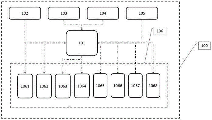
[0061] Such as figure 1 As shown, a compound wing UAV autopilot 100 includes a controller 101, a signal acquisition module and an actuator signal output module 106, and the signal input end of the controller 101 is connected to the data output end of the signal acquisition module , the signal acquisition end of the actuator signal output module 106 is connected to the data output end of the controller 101. The controller 101 includes a data processor and a data fusion module. In the signal acquisition module, more than one acquisition When the unit collects the same signal, the signal output terminals of the acquisition unit for this signal are all connected to the input terminal of the data fusion module, and the data fusion module performs data fusion on the obtained data to obtain unique state data, and then transmits the state data to data processor.
[0062] Specifically, in the above pilot scheme, the set controller 101 is used for data processing, the set signal acquis...
Embodiment 2
[0068] The present embodiment is further limited on the basis of embodiment 1, as figure 1 As shown, as a further technical solution of the compound wing UAV autopilot 100 described above: as a specific implementation of the signal acquisition module, the signal acquisition module includes at least one inertial sensor module 102, at least one dynamic and static pressure Sensor module 103, at least one magnetic field sensor module 104, at least one GPS module 105, the inertial sensor module is used to measure acceleration and angular velocity, the dynamic and static pressure sensor module 103 is used to measure dynamic pressure and static pressure, the GPS module 105 For measuring pseudo-range observation values, the magnetic field sensor module 104 is used for measuring magnetic field strength. The specific implementation scheme of the above signal acquisition module can collect a plurality of parameters in the flight process of the unmanned aerial vehicle. The parameters coll...
Embodiment 3
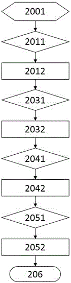
[0077] Such as figure 2 , the present embodiment also provides a control method adopted by the compound wing UAV autopilot 100, which is used for the compound wing UAV with horizontal propellers, three groups of aerodynamic rudder surfaces and multiple vertical propellers on the fuselage. Flight attitude control, each group of aerodynamic rudder surfaces are used to change the roll, pitch and yaw moment of the compound wing UAV respectively, the realization of the control method depends on any one of the automatic driving provided by any one of the above embodiments Instrument scheme, described control method comprises the following steps carried out in sequence:
[0078] Step 1, take off vertically;
[0079] Step 2, composite acceleration;
[0080] Step 3, fixed-wing flight;
[0081] Step 4, composite deceleration;
[0082] Step five, vertical landing;
[0083] The implementation of the compound acceleration step is: the criterion at the beginning of step 2 is that the ...
PUM
 Abstract
Description
Claims
Application Information