UPFC line side reactive power flow optimization control method

An optimized control and line-side technology, applied in the direction of reactive power adjustment/elimination/compensation, flexible AC transmission system, AC network with the same frequency from different sources, etc., can solve the problem of large active power, sending end and receiving end power grid Reduced voltage stability, reduced regulation ability, etc., to achieve the effect of small active power, enhanced voltage stability, and improved control ability

Active Publication Date: 2016-08-31
XJ ELECTRIC +3
View PDF2 Cites 6 Cited by
  • Summary
  • Abstract
  • Description
  • Claims
  • Application Information

AI Technical Summary

Problems solved by technology

When this kind of reactive power flow control is adopted, the ability of UPFC to adjust the active power flow of the line is reduced, and the reactive power loss of the line is provided by the power supply at the receiving end, and t...

Method used


Image

  • UPFC line side reactive power flow optimization control method
  • UPFC line side reactive power flow optimization control method
  • UPFC line side reactive power flow optimization control method

Examples


Embodiment Construction

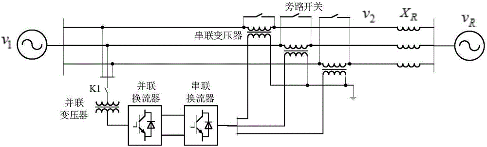
[0017] The UPFC line side reactive power flow optimization control method provided by the present invention comprises the following steps:

[0018] (1) Calculate the line reactive power flow command on the UPFC series side according to the effective value of the line current and the grid impedance;

[0019] (2) The closed-loop control of the reactive power of the power grid at the sending end is used to obtain the reactive power command of the converter on the parallel side of the UPFC.

[0020] Such as Figure 4 As shown, specifically, the calculation method of the line reactive power flow command on the UPFC series side is Q ref_se =3I lrms 2 x R , where: X R is the line impedance, I lrms is the effective value of the line current. The reactive power command of the parallel side converter is obtained by using the closed-loop control of the PI regulator according to the difference between the reactive power of the power grid at the sending end and zero.

[0021] Q re...


PUM


Abstract

The invention relates to a UPFC line side reactive power flow optimization control method. The core idea is that reactive power consumed by lines is provided by a UPFC, and the sending end and receiving end power grids do not provide reactive power. The method comprises the following steps: calculating the reactive power loss of a line according to the current effective value of the line and the power grid impedance, and taking the reactive power loss as a line reactive power flow instruction of a series side converter of a UPFC; and performing subtraction between the reactive power of a sending end power grid and zero, and carrying out closed-loop control to get a reactive power instruction of a parallel side converter. Through the method, the capability of the UPFC to control the active power flow of lines is enhanced under constant capacity of the UPFC. Moreover, as the UPFC provides reactive power for lines, the influence of the reactive power loss of lines to the power grid voltage is reduced, and the stability of the sending end and receiving end power grids is improved.

Description

technical field [0001] The invention relates to a reactive power flow optimization control method on a UPFC line side, and belongs to the field of flexible power transmission of electric power systems. Background technique [0002] The unified power flow controller (UPFC) is a series-parallel hybrid FACTS device based on voltage source converters, which can quickly, flexibly and continuously adjust the power flow of the line and improve the uneven distribution of power flow in the transmission section. Improving the utilization efficiency of transmission lines can also inject reactive power into the grid, stabilize system node voltages, and improve power supply reliability. [0003] Line flow control system such as figure 1 As shown, it consists of parallel transformers, parallel converters, series transformers, series converters and bypass switches. Parallel converters are used to stabilize the DC bus voltage of the converters and inject or absorb reactive power into the ...

Claims


Application Information

Patent Timeline
IPC IPC(8): H02J3/06H02J3/18
CPCH02J3/06H02J3/18Y02E40/10
Inventor 姚为正冯宇鹏吴金龙郝俊芳刘欣和李道洋王先为杨美娟
Owner XJ ELECTRIC
Why Eureka
Try Eureka