
LCL filterer passive resonance damping circuit and method

A damping circuit and damping resistance technology, applied in electrical components, output power conversion devices, etc., can solve the problem of easy resonance of LCL filters, and achieve the effect of suppressing resonance, reducing loss, and facilitating resonance suppression and transformation.

Inactive Publication Date: 2016-08-31
NARI TECH CO LTD +3
View PDF3 Cites 6 Cited by
  • Summary
  • Abstract
  • Description
  • Claims
  • Application Information

AI Technical Summary

Problems solved by technology

[0005] Purpose of the invention: In order to solve the problem that the LCL filter in the prior art is easy to resonate, the present invention provides a passive resonance damping circuit for the LCL filter

Method used


Image

  • LCL filterer passive resonance damping circuit and method
  • LCL filterer passive resonance damping circuit and method
  • LCL filterer passive resonance damping circuit and method

Examples


Embodiment Construction

[0015] The present invention will be further described below in combination with the accompanying drawings and specific embodiments.

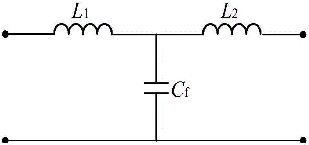
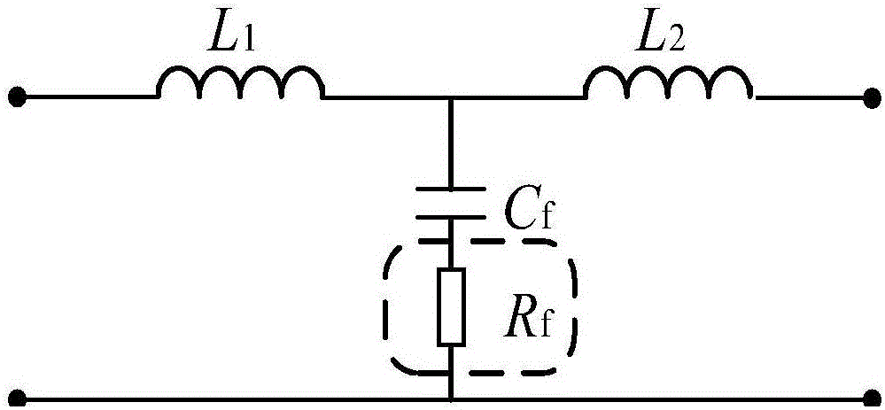
[0016] like figure 1 As shown, the LCL filter includes a filter inductor L 1 , filter inductance L 2 and filter capacitor C f . The filter inductor L 1 One end is connected to the inverter, and the other end is connected to the filter inductor L 2 One end and the filter capacitor C f Connected to one end of the filter inductor L 2 The other end is connected to the power grid, and the filter capacitor C f The other end of the inverter is connected to the other end of the inverter and the other end of the grid. Its transfer function is shown in formula (1):

[0017] G L C L ( s ) = i g ( s ...


PUM


Abstract

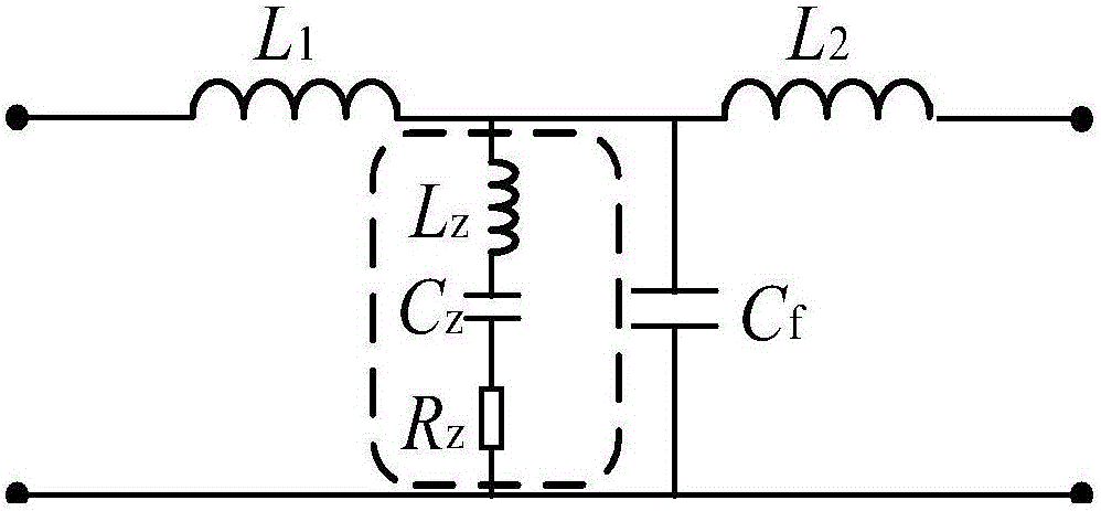
The invention discloses an LCL filterer passive resonance damping circuit and method, and the circuit comprises an LCL filter and an LCR branch circuit. The LCL filter comprises a filter capacitor Cf, and the LCR branch circuit is in parallel connection with the filter capacitor Cf. The LCR branch circuit comprises a damping inductor Lz, a damping capacitor Cz, and a damping resistor Rz, wherein the damping inductor Lz, the damping capacitor Cz and the damping resistor Rz are in series connection. The LCR branch circuit presents pure resistor characteristics at a resonant frequency, provides damping for a system, and inhibits the resonance. A damping unit presents large capacitive reactance characteristics at a power grid fundamental frequency, and a passing current is smaller. The fundamental wave loss of a damping resistor is greatly reduced. The circuit achieves the inhibition of filter resonance under lower power loss, and a parallel installation mode does not change an original filter electrical node, thereby facilitating resonance inhibition change of an existing LCL filter.

Description

technical field [0001] The invention relates to the technical field of power electronics, in particular to an outlet filter of a voltage source type grid-connected inverter. Background technique [0002] With the rapid development of full-control switching devices, a large number of new energy power generation equipment uses voltage source converters (VSC, Voltage Source Converter) to connect to the grid. VSC usually adopts PWM method to realize the control of grid-connected voltage and current. The principle is to use pulse waves with equal amplitudes to equivalent sinusoidal waveforms. In order to reduce the incoming harmonics, it is necessary to add a filter at the outlet of the inverter. At present, LCL or LC filters are widely used, taking into account the equivalent impedance of the power grid. The LC filter of VSC and the power grid form an LCL topology. [0003] The LCL filter belongs to the third-order filter, which has strong harmonic attenuation ability in the hi...

Claims


Application Information

Patent Timeline
IPC IPC(8): H02M1/12
CPCH02M1/126
Inventor 吴维宁赵紫龙邵宜祥石磊过亮瞿兴鸿孙素娟张侃王瑞
Owner NARI TECH CO LTD
Learn More