Three-phase voltage type PWM rectifier startup inrush current suppression method

A technology of starting inrush current and three-phase voltage, applied in the direction of electrical components, output power conversion devices, etc., can solve the problems of inrush current burning, burning wires, poor effect, etc.

Active Publication Date: 2016-08-31
HARBIN INST OF TECH
View PDF4 Cites 8 Cited by
  • Summary
  • Abstract
  • Description
  • Claims
  • Application Information

AI Technical Summary

Problems solved by technology

[0005] The present invention proposes a three-phase voltage type PWM rectifier start-up surge current suppression method, which is to solve the problem of burning the inductance, burning the insulation layer of the wire and damaging the switching...

Method used


Image

  • Three-phase voltage type PWM rectifier startup inrush current suppression method
  • Three-phase voltage type PWM rectifier startup inrush current suppression method
  • Three-phase voltage type PWM rectifier startup inrush current suppression method

Examples


specific Embodiment approach 1

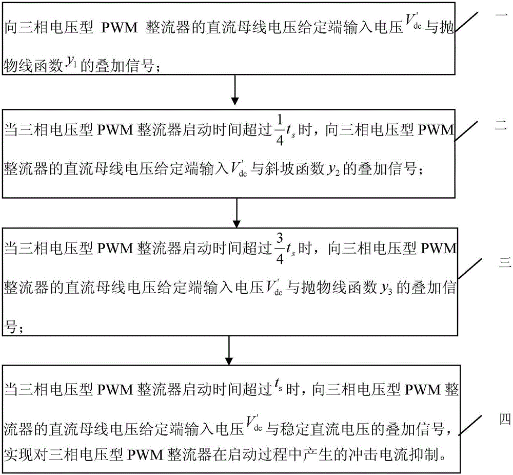
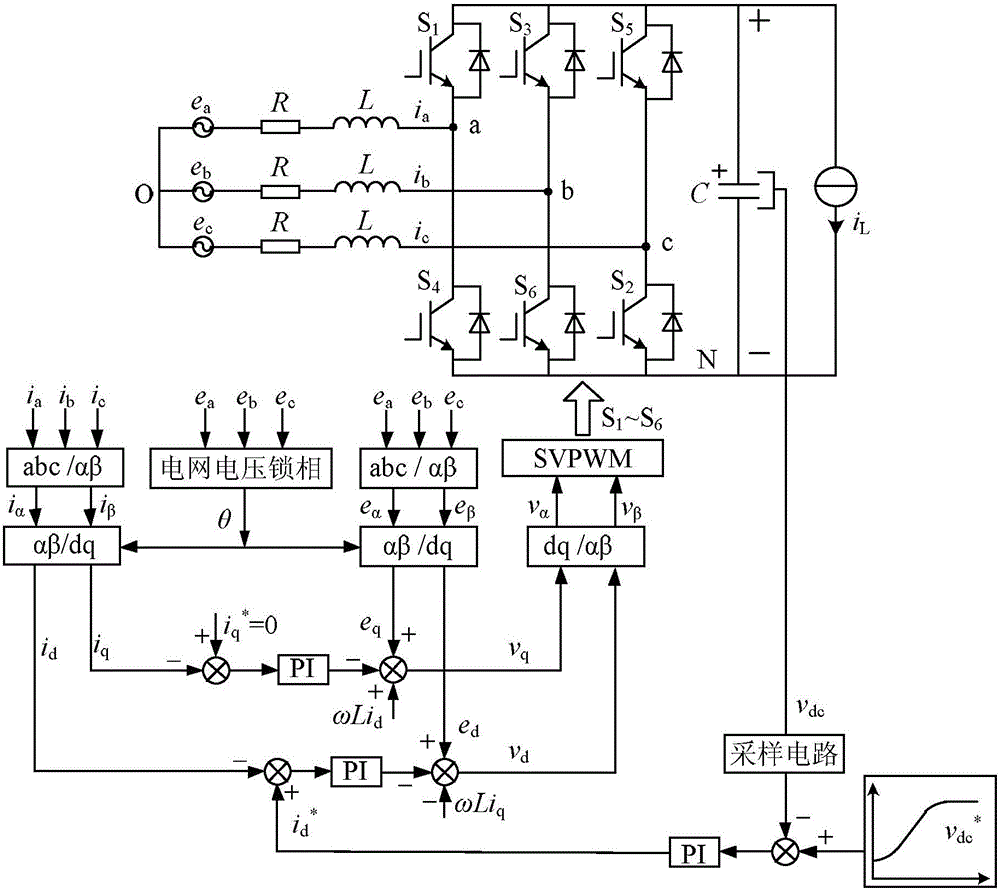
[0021] Specific implementation mode one, combination figure 1 , figure 2 with image 3 This embodiment will be described. The method for suppressing the starting impulse current of a three-phase voltage-type PWM rectifier described in this embodiment is used to suppress the inrush current generated by the three-phase voltage-type PWM rectifier during the starting process. The specific steps of the method are for:

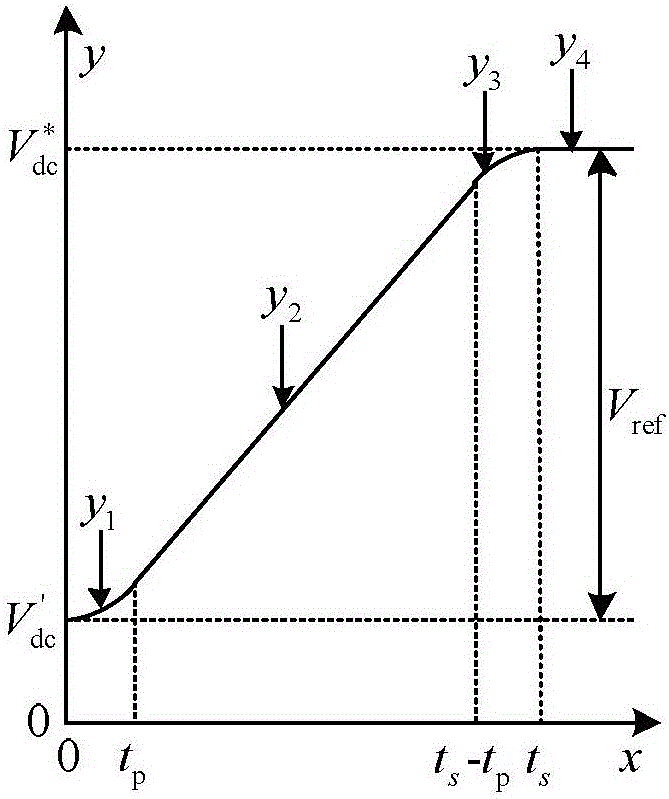
[0022] Step 1: Input voltage V′ to the DC bus voltage given terminal of the three-phase voltage type PWM rectifier dc With parabolic function y 1 Superimposed signal;

[0023] The parabolic function: Where x 1 Is the parabolic function y 1 And voltage V′ dc The duration of superimposed input to the given terminal of the DC bus voltage of the three-phase voltage type PWM rectifier, among them, Is the expected value of DC bus voltage, t s Is the time for the given value to increase to the expected value; the V' dc It is the DC bus voltage of the three-phase voltage ty...

specific Embodiment approach 2

[0029] Specific implementation manner 2. This implementation manner is a further description of a three-phase voltage type PWM rectifier starting impulse current suppression method described in the specific implementation manner 1. The stable DC voltage signal in step four is: y 4 =V ref .

[0030] In order to verify the practical application effect of the proposed three-phase voltage-type PWM rectifier starting impulse current suppression method, related experiments were carried out. The overall control block diagram of the system is as follows image 3 Shown. Figure 4 The starting waveform of the given step is given. Figure 5 Given to join the given curve, and the start time t s It is the starting waveform at 12ms. Image 6 Given to join the given curve, and the start time t s It is the starting waveform at 40ms.

[0031] Compared Figure 4 , Figure 5 with Image 6 It can be obtained that when the step is given, the starting inrush current can reach 3 times of the current peak...


PUM


Abstract

The invention provides a three-phase voltage type PWM rectifier startup inrush current suppression method, relates to the technical field of three-phase voltage type PWM rectifier startup, and solves the problems of burnout of electric inductors, burnout of the insulating layer of leads and damage to switching device caused by inrush current generated in the startup process of an existing PWM rectifier or the phenomena that control is complex and the effect is poor and damage caused by inrush current on the rectifier cannot be completely eliminated. A superposition signal of input voltage V'dc and a parabolic function y1, a superposition signal of voltage V'dc and a ramp function y2, a superposition signal of voltage V'dc and a parabolic function y3 and a superposition signal of voltage V'dc and DC stable voltage Vref are inputted to the DC bus voltage given end of a three-phase voltage type PWM rectifier in turn so that suppression of inrush current generated in the startup process of the three-phase voltage type PWM rectifier can be realized. The three-phase voltage type PWM rectifier startup inrush current suppression method is suitable for suppressing startup inrush current of the three-phase voltage type PWM rectifier.

Description

Technical field [0001] The invention relates to the technical field of starting a three-phase voltage type PWM rectifier. Background technique [0002] The PWM rectifier changes from three-phase uncontrolled rectification to PWM rectification at the moment of starting, the DC voltage is given And instantaneous voltage v dc There is a certain deviation, after the proportional amplification and limiting of the voltage outer loop PI regulator, a larger given value of d-axis current is obtained The given value and the instantaneous current i d After the difference is made, the proportional amplification and limiting of the PI regulator in the current inner loop are carried out to make the d-axis current change rate large, which is reflected in the current impact. It can be seen that the PWM rectifier start-up impulse current is amplified and limited by the PI regulator twice. If it is not suppressed, it will cause excessive system current, burn the insulation layer of the inductor a...

Claims


Application Information

Patent Timeline
IPC IPC(8): H02M1/32H02M1/36
CPCH02M1/32H02M1/36
Inventor 贲洪奇白银龙刘博
Owner HARBIN INST OF TECH
Why Eureka
Try Eureka