Device and method of inhibiting potential induced degeneration

A potential-induced attenuation, photovoltaic system technology, applied in circuit devices, output power conversion devices, circuits, etc., can solve problems such as high cost and affect the reliability of photovoltaic systems, and achieve low cost, low power consumption, and small capacity. Effect

Active Publication Date: 2016-08-31
SUNGROW POWER SUPPLY CO LTD
View PDF5 Cites 16 Cited by
  • Summary
  • Abstract
  • Description
  • Claims
  • Application Information

AI Technical Summary

Problems solved by technology

[0004] In the prior art, a voltage compensation device is added on the DC side of the photovoltaic system. For a photovoltaic system with multiple photovoltaic inverters connected in parallel on the AC side, it is necessary to add a voltage compensation device on the DC side of each photovoltaic inverter, so the cost is high In addition, there may be circulating currents between multiple voltage compensation devices, which will affect the reliability of the photovoltaic system

Method used


Image

  • Device and method of inhibiting potential induced degeneration
  • Device and method of inhibiting potential induced degeneration
  • Device and method of inhibiting potential induced degeneration

Examples


Embodiment 1

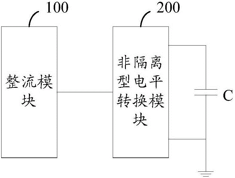
[0057] see Figure 1a and Figure 1b , which is a schematic diagram of Embodiment 1 of the device for suppressing potential-induced decay provided by the present invention.

[0058] The device for suppressing potential-induced attenuation provided in this embodiment is connected between the AC output terminal of the converter in the photovoltaic system and the grid-connected power frequency transformer; the device includes: a rectifier module 100, a non-isolated level conversion module 200 and at least one capacitor C;

[0059] like Figure 1a As shown, the input end of the rectification module 100 is connected to the output end of the converter; the rectification module 100 is used to rectify the alternating current output by the converter into direct current; the non-isolated level conversion A module 200, configured to perform level conversion on the direct current output by the rectification module; the level conversion is step-up conversion or voltage reverse conversion;...

Embodiment 2

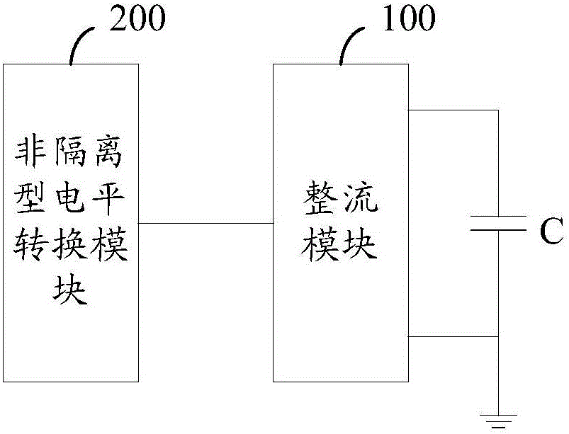
[0067] see Figure 2a and Figure 2b , which is a schematic diagram of the second embodiment of the device provided by the present invention.

[0068] In this embodiment, when the input end of the rectification module 100 is connected to the output end of the converter: the non-isolated level conversion module is specifically any one of the following: Boost circuit, Buck-boost circuit , Cuk circuit, Sepic circuit and Zeta circuit.

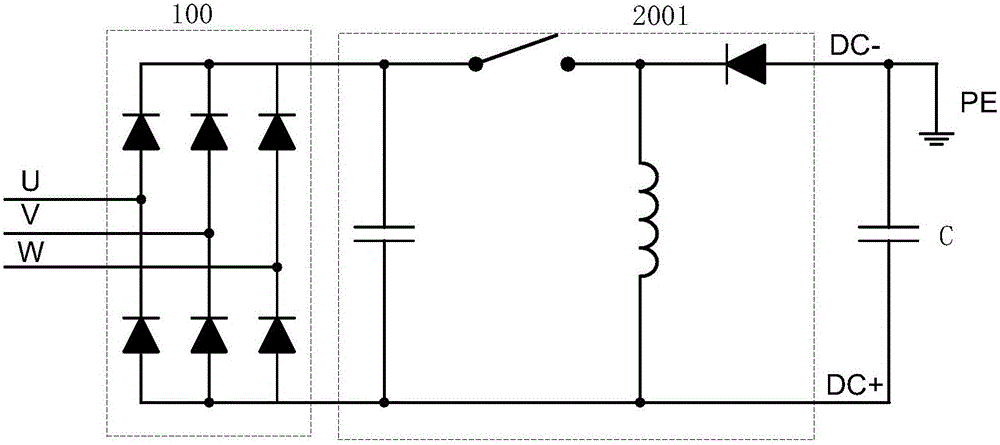
[0069] It should be noted that in this embodiment, the rectification module 100 is an uncontrolled rectification bridge as an example for introduction. like Figure 2a As shown, the uncontrolled rectifier bridge is a three-phase full-bridge circuit.

[0070] In this embodiment, the buck-boost circuit 2001 is introduced as the non-isolated level conversion module; the output terminal of the buck-boost circuit 2001 is connected in parallel with the capacitor C;

[0071] When the positive pole of the capacitor C is grounded, the voltage of the ph...

Embodiment 3

[0079] see Figure 4a and Figure 4b , which is a schematic diagram of Embodiment 3 of the device provided by the present invention.

[0080] In the device provided in this embodiment, when the input end of the rectification module 100 is connected to the output end of the converter: the non-isolated level conversion module is a Boost circuit 2002; the output ends of the Boost circuit 2002 are connected in parallel The capacitance C;

[0081] like Figure 4a As shown, when the negative electrode of the capacitor C is grounded, the voltage of the photovoltaic system to the ground is positive by controlling the output voltage of the non-isolated level conversion module.

[0082] like Figure 4b As shown, when the positive pole of the capacitor C is grounded, the voltage of the photovoltaic system to ground is negative by controlling the output voltage of the non-isolated level conversion module.

[0083] Combine below Figure 5a illustrate Figure 4a The device provided c...


PUM


Abstract

The invention provides a device and method of inhibiting potential induced degeneration (PID). The device is connected between the alternating current output terminal of a current transformer and a grid connected power frequency transformer, and comprises a rectification module, a non-isolated level conversion module and at least one capacitor. The input terminal of the rectification module is in connection with the output terminal of the current transformer; the rectification module rectifies the alternating current outputted by the current transformer into direct current; the non-isolated level conversion module performs level conversion on the direct current outputted by the rectification module; level conversion is boost conversion or voltage reverse conversion; or, the input terminal of the non-isolated level conversion module is in connection with the output terminal of the current transformer; the non-isolated level conversion module is used for performing level conversion on the alternating current outputted by the current transformer, and level converted is boost conversion; the rectification module rectifies the alternating current outputted by the non-isolated level conversion module into direct current; a capacitor is in parallel connection with the output terminal of direct current, and the anode or cathode of the capacitor is grounding. The device can avoid or decrease photovoltaic cell panel PID effects.

Description

technical field [0001] The invention relates to the technical field of photovoltaic power generation, in particular to a device and system for suppressing potential-induced attenuation. Background technique [0002] Potential Induced Degradation (PID, Potential Induced Degradation) refers to the attenuation of output characteristics of certain types of photovoltaic panels due to potential induction at a specific ground voltage. The PID effect will lead to a decrease in the output power of the photovoltaic system. [0003] Therefore, in order to prevent or weaken the PID effect, it is necessary to compensate the ground voltage of the photovoltaic system so that the bias voltage of the photovoltaic cell panel to the ground is in a region where the PID effect does not occur. [0004] In the prior art, a voltage compensation device is added on the DC side of the photovoltaic system. For a photovoltaic system with multiple photovoltaic inverters connected in parallel on the AC s...

Claims


Application Information

Patent Timeline
Patent Type & Authority Applications(China)
IPC IPC(8): H02S40/32
CPCH02S40/32H02J3/381H02J2300/24H02M3/335H02M7/00Y02E10/56H01F38/42H02J3/38H02M3/005H02M3/24H02M7/06H02M7/217
Inventor 俞雁飞倪华杨宗军代尚方
Owner SUNGROW POWER SUPPLY CO LTD
Why Eureka
Try Eureka