Spray distillation device

A technology of distillation device and evaporation chamber, which is applied in the direction of spray evaporation, etc., can solve the problems of large energy consumption and waste liquid not meeting the national environmental protection requirements, and achieve the effect of fast contact speed

Inactive Publication Date: 2016-09-07
YANSHAN UNIV
View PDF5 Cites 10 Cited by
  • Summary
  • Abstract
  • Description
  • Claims
  • Application Information

AI Technical Summary

Problems solved by technology

However, the distillation (rectification) process realized by the distillation tower in the prior art not only needs to consume a large amount of energy when evaporating and treating the reflux, but also the waste liquid discharged often does not meet the national environmental protection requirements

Method used


Image

  • Spray distillation device
  • Spray distillation device
  • Spray distillation device

Examples


Embodiment 1

[0033] Embodiment 1: there is tower spray distillation bed system

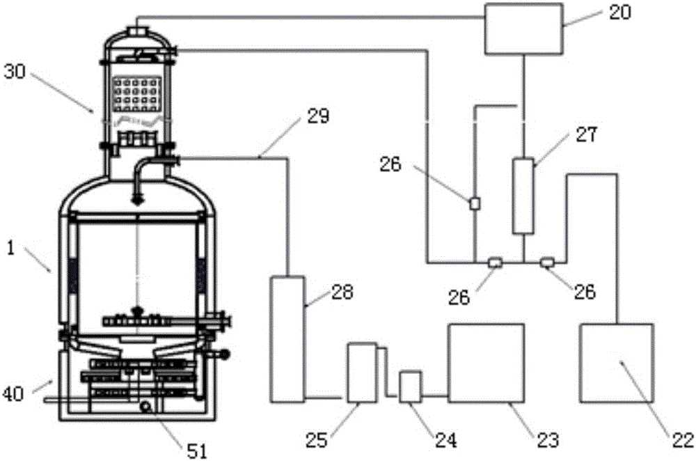
[0034] The spray distillation device of the present invention includes an evaporation chamber 1, a rectification column 30, a raffinate processor 40, a condenser 20, a raw material liquid storage tank 23, a finished product storage tank 22, a pump 24, a filter 25, and a raw material preheater 28. Finished product cooler 27, the above-mentioned equipment is composed of pipeline 29 and valve 26 as figure 2 Shown is a column spray distillation bed system.

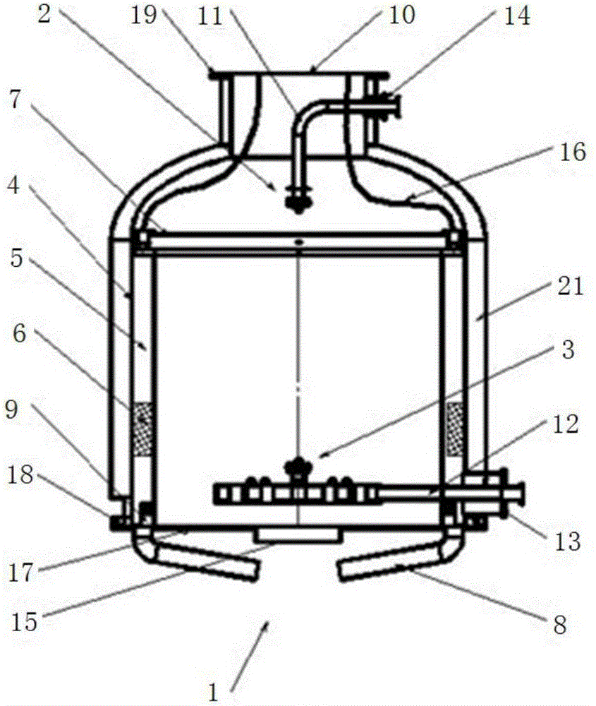
[0035] Such as figure 1 As shown, the evaporation chamber 1 includes a raw material liquid atomizer 2, a water vapor distributor 3, a housing 4 and a reflux liquid treatment device 5; the top of the housing 4 has a volatile phase outlet 10 and a tower shell bottom of a rectification column 30 Connected through a small flange 19; the reflux conduit 16 of the evaporation chamber 1 is connected to the raffinate outlet 36 of the rectification column 30; the bot...

Embodiment 2

[0045] Embodiment 2: spray distillation bed system

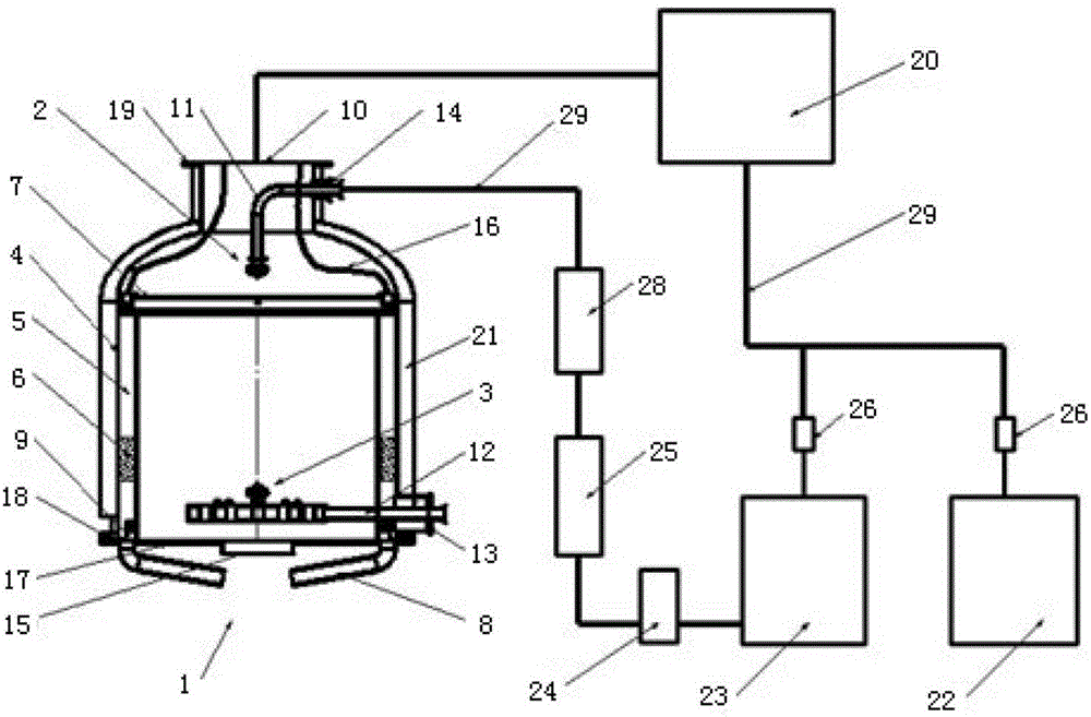
[0046] refer to figure 1 , image 3 , Figure 6-13 , the spray distillation device of the present invention, it comprises evaporation chamber 1, condenser 20, raw material liquid storage tank 23, finished product storage tank 22, pump 24, filter 25 and raw material liquid preheater 28, above-mentioned equipment passes pipeline 29 and valve 26 connected as image 3 The spray distillation bed system shown.

[0047] The structural functions of each component in this embodiment have been described in Embodiment 1. Here is a specific description of the specific working process of this simple spray distillation bed system:

[0048] The raw material mixed liquid stored in the raw material liquid storage tank 23 is driven into the raw material liquid atomizer 2 through the pump 24, the filter 25, the raw material liquid preheater 28, the pipeline 29 and the raw material liquid feeding pipe 11, and after atomization Converging ...

Embodiment 3

[0050] Embodiment 3: no tower spray distillation bed system

[0051] combine figure 1 with Figure 14 , briefly describe the use of two evaporation chambers (spray rectification beds) in series. Parts that are the same as those in the foregoing embodiments will not be described again. The descriptions are different or slightly changed as follows:

[0052] 1. The center hole of the mounting plate 17 of the previous evaporation chamber 1, that is, the outlet 15 of the difficult-to-volatile phase is raised up with a circle of cofferdams. The purpose is that the liquid that has not been evaporated does not flow down through this hole, but flows down from the residual liquid discharge pipe 8 , into the filler mesh circle 6 below.

[0053] 2. Connect a short pipe welding flange 19 under the mounting plate 17 to connect it with the evaporation chamber flange 19 below. The purpose is to ensure that the steam below enters the last evaporation chamber 1 through the less volatile ph...


PUM


Abstract

The invention discloses a spray distillation device, which comprises at least one evaporation chamber, a feed solution inlet pipe, a raw material preheater, a filter, a pump, a feed solution storage tank and a finished product storage tank, wherein the evaporation chamber comprises a shell, a feed solution atomizer, a water vapor distributor and a reflux treatment device; an easy-to-volatilize phase outlet is formed in the top of the shell, and a difficult-to-volatilize phase outlet is formed in the bottom; the feed solution atomizer and the water vapor distributor are mounted in the shell; the feed solution atomizer is connected with the feed solution inlet pipe; the water vapor distributor is connected with a water vapor inlet pipe; the reflux treatment device is mounted in the shell, and consists of a reflux conduit, a water spraying ring, a filler net loop, a residual liquid ventilation cap, a residual liquid discharge pipe and a mounting plate. According to the spray distillation device, a spray distillation technology is adopted instead of an existing mass and heat transfer distillation manner employing an orifice plate or a filler as a main condition, so that heat energy can be completely and effectively utilized, energy resources can be saved, waste liquid discharge reaches the standard, and prominent effects are achieved.

Description

technical field [0001] The invention relates to distillation equipment, in particular to a distillation (rectification) device. technical background [0002] Distillation is the process of heating the mixed liquid to be separated to boiling, drawing out the generated vapor, and then condensing it, resulting in a liquid different from the original mixed liquid. Rectification is a distillation with an ascending vapor and an oncoming descending flowing liquid (reflux) interacting as the process proceeds. The above-mentioned distillation and rectification are usually referred to simply as distillation. [0003] The main equipment of traditional distillation are: distillation tower, reboiler, condenser, reflux conveying equipment, etc. The main space condition for mass transfer and heat transfer is tray or packing. After the liquid mixture enters the distillation tower, the volatile phase gradually concentrates toward the top of the tower, and after leaving the top of the towe...

Claims


Application Information

Patent Timeline
Patent Type & Authority Applications(China)
IPC IPC(8): B01D1/16
CPCB01D1/16
Inventor 邢继春
Owner YANSHAN UNIV
Why Eureka
Try Eureka