Molding machine for producing high-strength wood particles

A technology of wood pellets and molding machines, which is applied in the direction of raw material extrusion and granulation, which can solve the problems of easy pulverization, inconvenient replacement of molds, unevenness of pressing rollers, etc., to achieve increased particle strength, increased extrusion strength, and improved The effect of granulation effect

Inactive Publication Date: 2016-09-07
HUZHOU TUOGAO MACHINERY CO LTD
View PDF7 Cites 3 Cited by
  • Summary
  • Abstract
  • Description
  • Claims
  • Application Information

AI Technical Summary

Problems solved by technology

[0003] Its disadvantage is that during the molding process of wood pellets, the pressing roller assembly squeezes the material between it and the ring die, and the reaction force of the ring die and the material on the pressing roller makes the pressing roller assembly appear to be opposite to the extrusion of the material. The direction of movement tends to cause the shaking of the pressing roller assembly, which affects the pressing stability, granulation effect and the service life of the pressing roller assembly, and due to the unevenness of the pressing roller, the wood pellets extruded from the extrusion port The length of the extruded particles is inconsistent, the strength of the extruded particles is not high, and it is easy to loosen
Although the shaking problem has been alleviated to a certain extent, it is inconvenient to disassemble and replace the mold, and the granulation effect has not been greatly improved. The granulation has not been cut and trimmed, the length of the granulation is inconsistent, and the strength of the granules is low. chalking

Method used


Image

  • Molding machine for producing high-strength wood particles
  • Molding machine for producing high-strength wood particles
  • Molding machine for producing high-strength wood particles

Examples


Embodiment 1

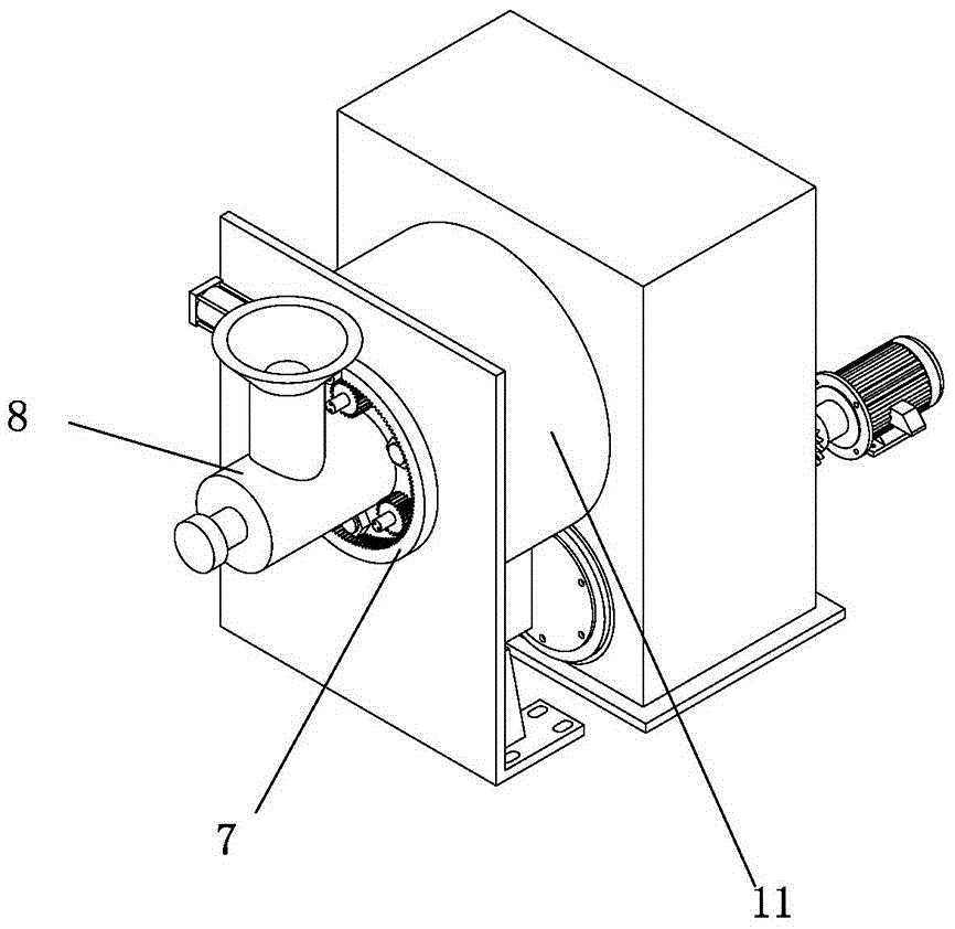
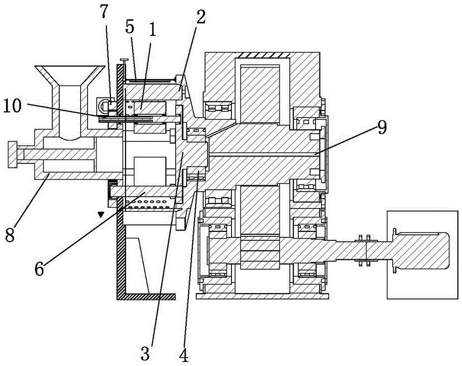
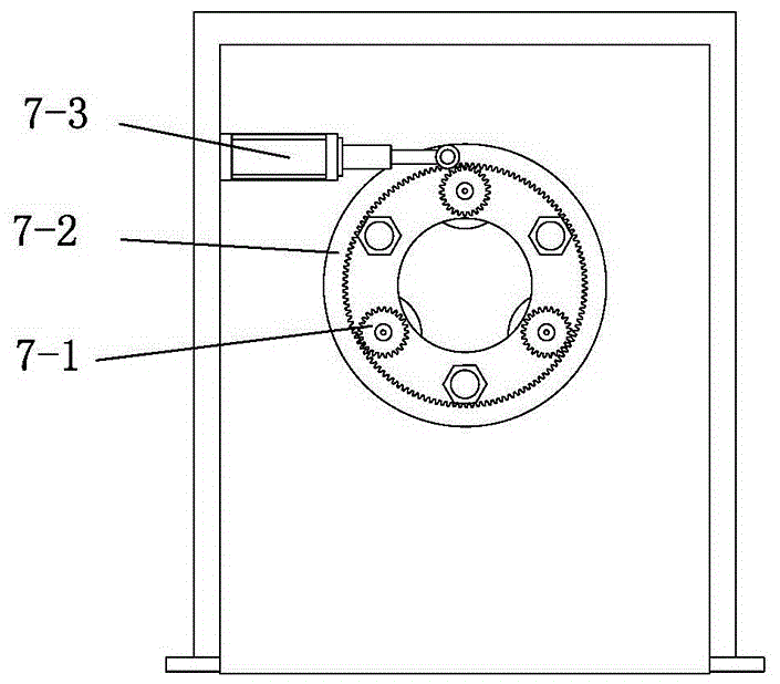
[0040] Embodiment 1: as figure 1 with figure 2 As shown, a molding machine for producing high-strength wood pellets includes a press wheel assembly 1, a mold assembly 2, a conversion joint 3, a main bearing 4, a moving cutting assembly 5, a fastening mechanism 6, an adjustment mechanism 7, and a feeding device 8 , The first cooling channel 9, the second cooling channel 10, the outer cover 11 and the clamping part 12;.

[0041] Such as Figure 5 As shown, the mold assembly 2 includes a main shaft 2-1 and an annular mold 2-2; one end of the annular mold 2-2 is embedded and fixed on the main shaft 2-1 through a clamping part 12, and the main shaft 2-1 and the annular mold 2-2 is kept concentric, and the main shaft 2-1 is provided with a guide surface 2-1-2 for its installation at the matching installation position with the ring mold 2-2; the ring mold 2-2 has a mold cavity , there are a certain number of biomass fuel particle extrusion ports 2-2-1 on the ring surface, and at ...


PUM


Abstract

The invention relates to a molding machine and particularly relates to a molding machine for producing high-strength wood particles. The molding machine for producing the high-strength wood particles comprises a compaction wheel assembly, a mold assembly, a conversion connector and a movable cutting assembly, wherein the compaction wheel assembly comprises a compaction wheel shaft, a compaction wheel and a bracket; the mold assembly comprises a main shaft and an annular mold; the annular mold is provided with a mold cavity; a plurality of extruding holes are formed in an annular surface; the movable cutting assembly comprises a screw rod arranged on the bracket, a movable nut which sleeves the screw rod, a slide rail arranged on the main shaft, a slide seat arranged on the slide rail and a cutting tool; one end of the cutting tool is fixed on the movable nut and the other end of the cutting tool is fixed on the slide seat; and each extruding hole comprises a material storage part and a molding part connected onto the material storage part. With the adoption of the molding machine, the length of the particles is consistent; the strength of the extruded particles is improved, the granulation effect is improved and the stress on the mold is relatively uniform; and the molding machine is simple in structure and convenient to operate and the service life of the equipment is prolonged.

Description

technical field [0001] The invention relates to a molding machine, in particular to a molding machine for producing high-strength wood pellets. technical background [0002] The ring die pellet mill includes a frame. Ring dies, rotors, press roll assemblies, support structures for press roll assemblies, spindles and infeed and outfeed components. The support structure of the pressure roller assembly of the ring die granulator includes a front plate and a rear plate. The pressure roller assembly is supported between the front plate and the rear plate through the pressure roller shaft, and the two ends of the pressure roller shaft are respectively supported on the front plate and the rear plate. and lock the pressure roller assembly through the pressure roller locking nut, and a pressure roller adjustment mechanism is provided on the pressure roller shaft and outside the two ends of the front plate. During work, the material enters the pressing chamber formed by the ring die...

Claims


Application Information

Patent Timeline
Patent Type & Authority Applications(China)
IPC IPC(8): B01J2/20
CPCB01J2/20
Inventor 屠丰田姜晓丽
Owner HUZHOU TUOGAO MACHINERY CO LTD
Why Eureka
Try Eureka