Supercharge Your Innovation With Domain-Expert AI Agents!

Machining method for rotary steel box girder

A processing method and technology of steel box girders, applied in the direction of metal processing equipment, beams, forming tools, etc., can solve the problems of potential safety hazards, reduced processing efficiency, large stair section, etc., to reduce work burden, improve processing efficiency, size high precision effect

Active Publication Date: 2016-09-07
CHINA METALLURGICAL CONSTR ENG GRP
View PDF8 Cites 1 Cited by
  • Summary
  • Abstract
  • Description
  • Claims
  • Application Information

AI Technical Summary

Problems solved by technology

At present, the main structure of the spiral staircase is divided into two types, one is column type, usually this kind of staircase is arranged around a single column, the plane is circular, its platform and steps are fan-shaped plane, the inner width of the steps is very small, and Forming a steeper slope, the stress point of this type of staircase is only a single column. When people walk on the outside of it, the pedals are in a shaking state, which poses a safety hazard. Only one or two people can pass, and it is suitable for various small buildings Middle; another kind is ring form, and this kind of stair comprises inner annular edge beam, outer annular edge beam and some pedals that are arranged between described inner annular edge beam and described outer annular edge beam, and such stair section is big, Able to carry a large flow of people
In order to meet the safety requirements in terms of strength, the inner and outer annular edge beams adopt steel box girder structure, but the steel box girder is in a curved and twisted shape as a whole. During the blanking process, it is difficult to locate the bent and twisted shape. The dimensional accuracy of the steel box girder after the bending and torsion shape is low, so the degree of bending and torsion of the steel box girder after processing is inconsistent, which leads to the incompatibility of the steel box girders on the inner and outer sides, making it impossible to complete the installation of the pedals, so that workers will be confused. The later adjustment of the steel box girder not only increases the workload of the workers, but also prolongs the installation time and reduces the processing efficiency

Method used


Image

  • Machining method for rotary steel box girder
  • Machining method for rotary steel box girder
  • Machining method for rotary steel box girder

Examples


Embodiment Construction

[0016] The present invention will be further described in detail below in conjunction with the accompanying drawings.

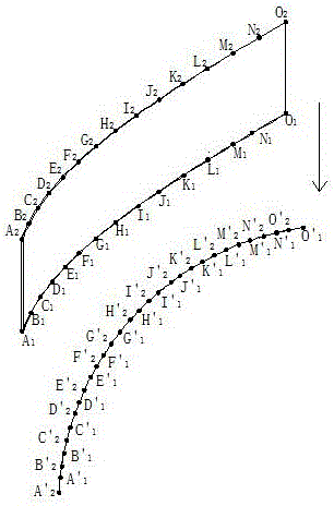
[0017] Such as Figure 1 to Figure 3 as shown, figure 1 The direction of the arrow in the figure is the projection direction of the upper side coordinate point and the lower side coordinate point. The processing method of the rotating steel box girder in this specific embodiment first draws a three-dimensional model according to the structural parameters of the inner plate of the steel box girder. In the model, the upper side of the inner plate is spaced along its length direction to establish the upper side coordinate point A 1 , B 1 、C 1 、D 1 ...O 1 , the lower side plate is spaced along its length direction to establish the lower side coordinate point A 2 , B 2 、C 2 、D 2 ...O 2 , and then respectively project the upper side coordinate point and the lower side coordinate point along the vertical direction onto the horizontal reference plane set be...


PUM


Abstract

The invention discloses a machining method for a rotary steel box girder. The machining method comprises the following steps: firstly drawing a three-dimensional model according to structural parameters of an inner side plate of the steel box girder; building coordinate points at intervals on the upper side and the lower side of the inner side plate in the three-dimensional model, projecting to obtain projection coordinate points, and obtaining projection lines according to projection link lines; subsequently manufacturing a machining mold for the rotary steel box girder according to the projection lines, determining location points on the machining mold for the rotary steel box girder according to the projection coordinate points; machining the inner side plate of the steel box girder according to the location points; subsequently positioning and welding a top plate and a base plate of the steel box girder, and positioning and welding the last piece of outer side plate according to three accomplished surfaces; finally fully welding junction seams. According to the machining method disclosed by the invention, a corresponding machining mold is manufactured according to the projection of the inner side plate of the steel box girder, and then the steel box girder is machined and manufactured according to the machining mold so that the steel box girder is simpler to machine and high in dimensional precision; bending-twisting molding can be finished at one time; after-treatment is not needed; the workload of a machining worker is alleviated; the machining efficiency is improved.

Description

technical field [0001] The invention relates to the field of processing of spiral stairs, in particular to a processing method of a rotating steel box girder. Background technique [0002] Spiral staircase is usually called spiral or spiral staircase. Because of its beautiful, elegant and elegant streamlined shape, it saves space. It is often used in office buildings and residential buildings with few floors, or as architectural sketches in courtyards or indoors. At present, the main structure of the spiral staircase is divided into two types, one is column type, usually this kind of staircase is arranged around a single column, the plane is circular, its platform and steps are fan-shaped plane, the inner width of the steps is very small, and Forming a steeper slope, the stress point of this type of staircase is only a single column. When people walk on the outside of it, the pedals are in a shaking state, which poses a safety hazard. Only one or two people can pass, and it ...

Claims


Application Information

Patent Timeline
Patent Type & Authority Applications(China)
IPC IPC(8): B21D37/20B21D47/01E04F11/022
CPCB21D37/20B21D47/01E04F11/022
Inventor 周敬宋林谢廷明
Owner CHINA METALLURGICAL CONSTR ENG GRP
Features
  • R&D
  • Intellectual Property
  • Life Sciences
  • Materials
  • Tech Scout
  • Unparalleled Data Quality
  • Higher Quality Content
  • 60% Fewer Hallucinations
Learn More