
Directional vibration wheel

A vibration wheel and vibration exciter technology, which is applied to roads, road repairs, roads, etc., can solve the problems of heavy component weight, unfavorable processing and manufacturing, and difficult processing, so as to facilitate design and manufacturing processing, save costs, and simplify vibration wheels structure effect

Active Publication Date: 2016-09-07
XCMG CONSTR MACHINERY
View PDF7 Cites 2 Cited by
  • Summary
  • Abstract
  • Description
  • Claims
  • Application Information

AI Technical Summary

Problems solved by technology

The vibrating wheel can only be assembled vertically and cannot be assembled horizontally, and the weight of the whole assembly is relatively heavy, so it is dangerous to lift
[0006] Second, the left and right ends of the entire assembly need two large bearings to support, the cost is high, and both bearings need to bear a large excitation force
The number of teeth of the gears in this transmission mode needs to be specially designed for coordination, and it is not conducive to equal strength design
The modulus of each gear is the same, but the number of teeth is different, which is also not conducive to processing and manufacturing
If transition gear 1 and transition gear 3 are integrated with the shaft, the processing will be particularly difficult, and it is necessary to process teeth with two parameters on one shaft. If it is assembled, the number of related parts will increase, which is not conducive to reliability.

Method used


Image

  • Directional vibration wheel
  • Directional vibration wheel
  • Directional vibration wheel

Examples


Embodiment Construction

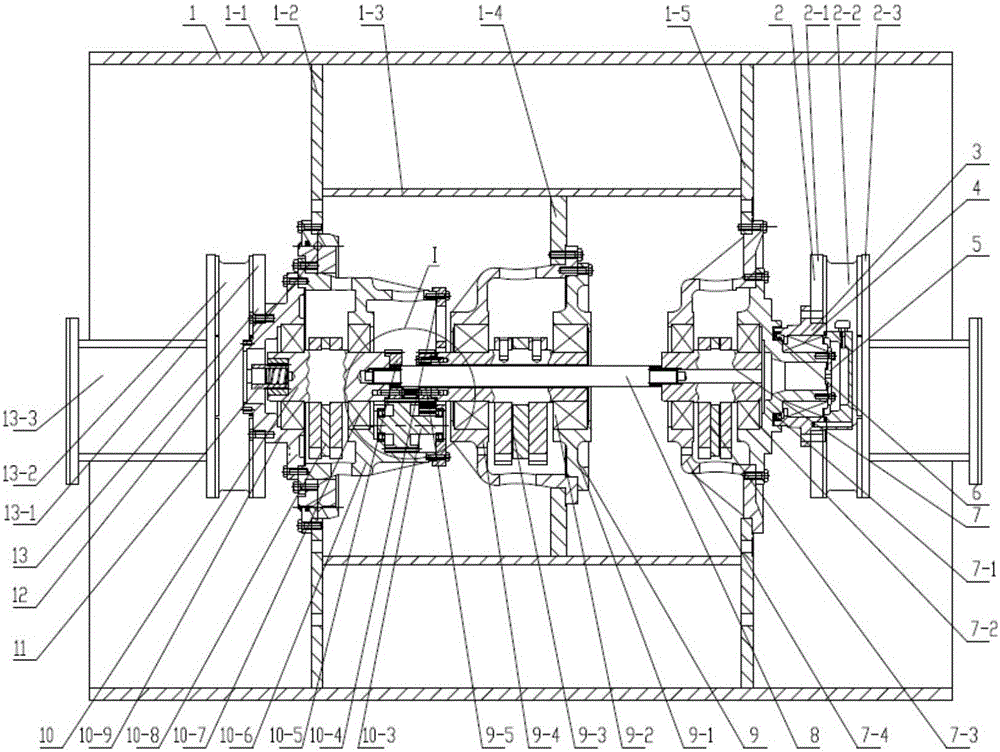
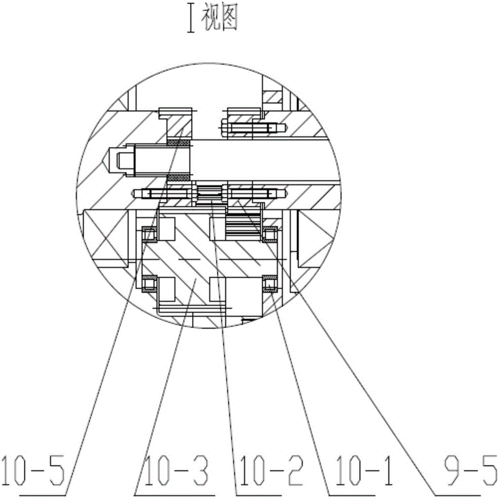
[0032] The technical scheme of the present invention will be described in further detail below in conjunction with the accompanying drawings and specific embodiments, so that those skilled in the art can better understand the present invention and implement it, but the examples given are not intended to limit the present invention.

[0033] like figure 2 and image 3 As shown, a directional vibrating wheel includes a vibrating wheel body 1. Preferably, the vibrating wheel body 1 consists of an outer ring 1-1, a left web 1-2, an inner ring 1-3, a middle web 1-4, and a right web 1-5 welded. like figure 2 As shown, the vibrating wheel body 1 includes an outer ring 1-1 and an inner ring 1-3 arranged coaxially, and the two ends of the inner ring 1-3 pass through the left web 1-2 and the right web 1-5 Connected with the outer ring 1-1, the inner ring 1-3 is provided with an intermediate vibration chamber 9, figure 2 Among them, the middle vibration chamber 9 is connected with...


PUM


Abstract

The invention discloses a directional vibration wheel. The directional vibration wheel comprises a vibration wheel body and is characterized in that the vibration wheel body comprises an outer ring and an inner ring which are coaxially arranged; the two end faces of the inner ring are connected with the outer ring through a left web and a right web correspondingly; a middle vibration chamber is arranged in the inner ring; a left vibration chamber and a right vibration chamber are arranged on the parts, located at the two ends the middle vibration chamber, of the vibration wheel body correspondingly; a transmission shaft penetrates through the middle vibration chamber to be connected with the left vibration chamber and the right vibration chamber; the left vibration chamber is supported on the vibration wheel body through a slewing bearing and connected to a vehicle frame through a left connecting assembly; and the right vibration chamber is connected to the vehicle frame through a right connecting assembly. The assemblability, reliability, maintainability, complexity, cost and the like of the directional vibration wheel are improved, and meanwhile the directional vibration wheel can be in butt joint with a direction variable vibration wheel rapidly.

Description

technical field [0001] The invention relates to a directional vibration wheel. Background technique [0002] The vibration generated by the vibratory roller makes the soil particles in a high-frequency state, the internal friction between the soil particles is lost, and the gravity of the roller itself exerts compressive stress and shearing force on the soil to rearrange the particles so that the soil is compacted. After years of development of vibratory rollers, the most popular vibrating wheel on the market is the circular vibrating wheel. The feature of the circular vibrating wheel is that the exciter is arranged along the axial direction of the vibrating wheel to form a periodic centrifugal force. Since the invention of the vibratory roller, the structure has been greatly developed and verified for many years, and the structure is extremely mature. [0003] As a new vibration mode, directional vibration has certain advantages over circular vibration in terms of compacti...

Claims


Application Information

Patent Timeline
Patent Type & Authority Applications(China)
IPC IPC(8): E01C19/28
CPCE01C19/28
Inventor 刘洁周保刚刘邦辉牛春亮夏磐夫谢娟娟江奎峰
Owner XCMG CONSTR MACHINERY
Learn More