A flow-making system for deep-water test pools

A deep-water test and pool technology, applied in the field of deep-sea engineering, can solve problems such as poor economy, lack of rectifiers, and inability to simulate high-quality flow fields, saving space and reducing costs.

Active Publication Date: 2018-01-23
DALIAN UNIV OF TECH
View PDF9 Cites 0 Cited by
  • Summary
  • Abstract
  • Description
  • Claims
  • Application Information

AI Technical Summary

Problems solved by technology

The form of horizontal circulation in the pool is to install a movable local flow-making device in the pool. The flow-making device can be equipped with multiple uniformly distributed high-speed water flow nozzles. The water flow circulates horizontally in the pool and finally forms a certain flow field in the test area. , the disadvantage of this flow-making system is that it is difficult to guarantee the uniformity and stability of the flow field in the pool, and it can only form a local flow field; It enters the pool through the pipeline and the water inlet corridor, and then returns to the pipeline through the water outlet corridor at the other end of the pool, forming a complete cycle process. When the water flows through the narrow pipeline, the loss is great, the power consumption is high, and the economy is relatively low. Poor; the flow-making system in the form of circulation around the false bottom (up and down circulation) relies on a high-power pump unit to pump or push water in the pool at one end of the pool below the false bottom, driving the surrounding water to circulate around the false bottom, thereby forming a Backflow, such as the Norwegian Marintek pool flow method, but it lacks corresponding rectification devices and cannot simulate high-quality flow fields

Method used


Image

  • A flow-making system for deep-water test pools
  • A flow-making system for deep-water test pools
  • A flow-making system for deep-water test pools

Examples


Embodiment Construction

[0013] The present invention will be further described below in conjunction with the drawings.

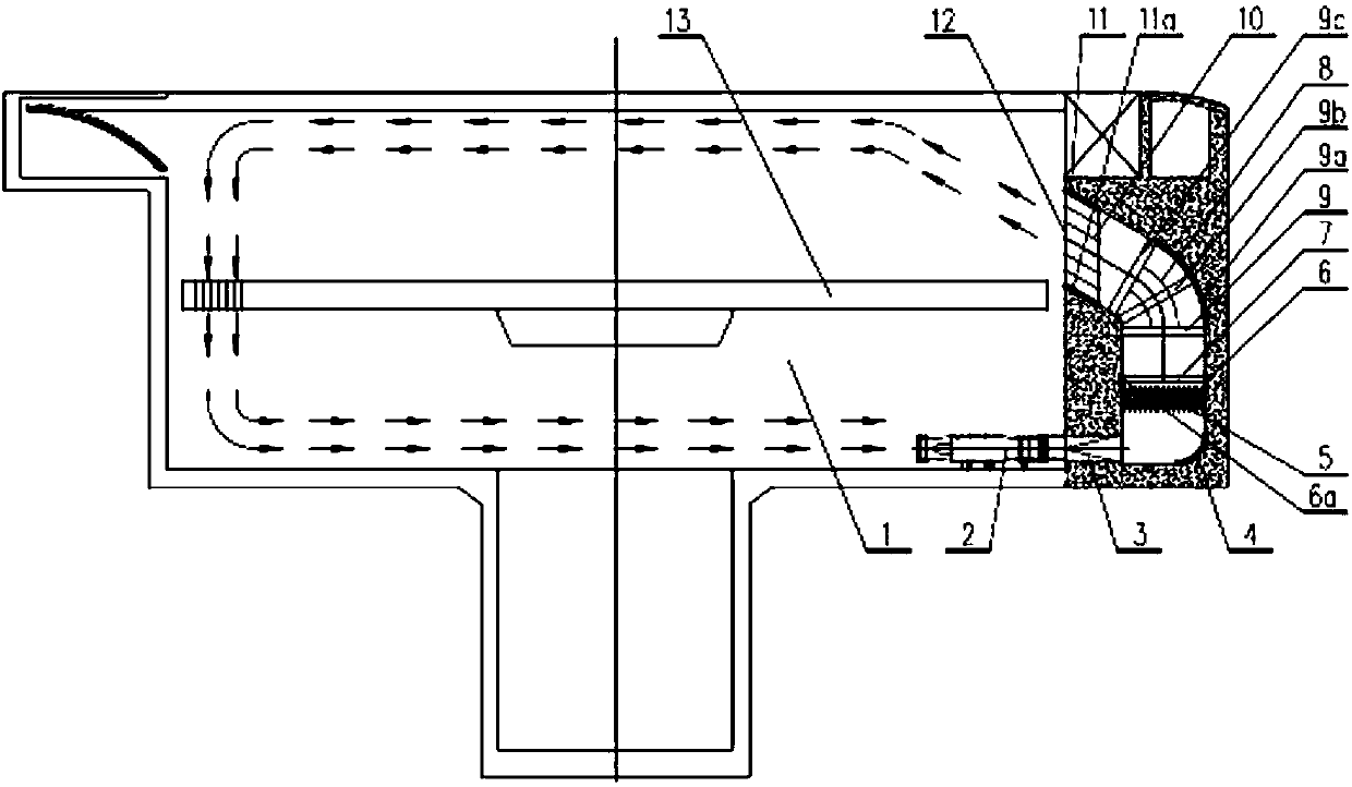
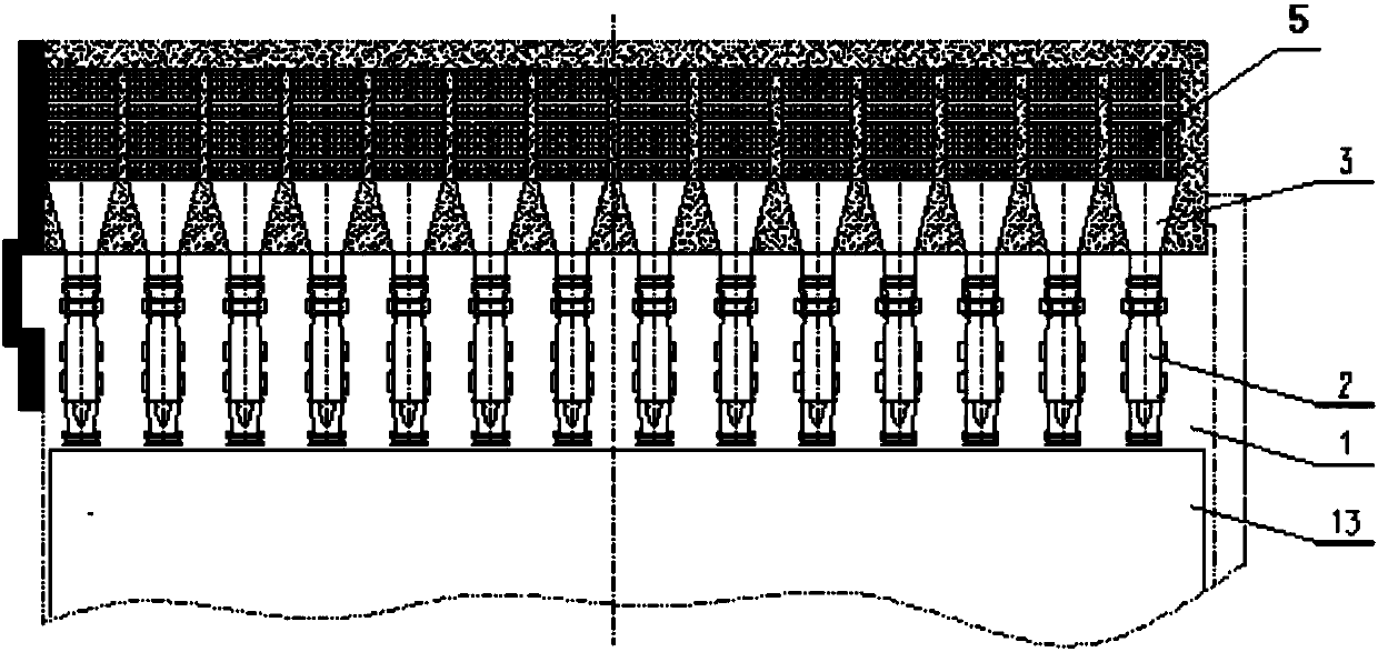
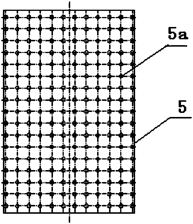
[0014] Such as figure 1 , 2 , 3, a flow generation system used in the deep water test pool, mainly including deep water pool 1, first, second, ... N-1, N round variable square connecting section 3, first, second, ... N- 1. N rectifying wall 5 and lifting platform 13, said deep water pool 1 is equipped with first, second, ... N-1, N flow pumps 2, and said first, second, ... N-1, N flow The water outlets of the water pump 2 are respectively connected to the first, second,...N-1, N round variable square connection section 3, and a rectifying baffle 7 is connected behind the first, second,...N-1, N rectifying wall 5, The rectifying baffle 7 is fixedly connected to the first and second embedded steel plates 6, 6a of the rectifying baffle, and the rectifying baffle 7 is provided with a number of flow-through holes, and is connected to the first, second,... The N-1 and N rectification walls...


PUM


Abstract

The invention relates to the technical field of deep sea engineering and provides a current generating system used in a deep water experiment pool. The current generating system mainly comprises the deep pool, round-to-square connecting sections, rectifying walls and a lifting platform. Current generating water pumps are installed in the deep pool. Water outlets of the current generating water pumps are connected with the round-to-square connecting sections. A rectifying baffle is jointed to the position behind the rectifying walls and fixedly connected to rectifying baffle embedded steel plates. A plurality of current passing holes corresponding to the rectifying walls are formed in the rectifying walls. A deflector is arranged behind the rectifying baffle and fixedly connected to deflector embedded steel plates, so that a diversion channel is formed. A diversion rail is arranged behind the deflector and installed on diversion rail embedded steel plates. A steel wire mesh is arranged behind the diversion rail and used for controlling turbulence in a current. According to the current generating system used in the deep water experiment pool, overall current generating in the pool is adopted, and water pump water outlet corridors and water suction pipelines are not needed, so that the space is saved, the cost is reduced, and meanwhile, the overall flow velocity target requirement is met.

Description

Technical field [0001] The invention relates to a flow generating system used in a deep-water test pool, belonging to the technical field of deep-sea engineering. Background technique [0002] In deep-sea development, offshore platforms and other structures must withstand the test of harsh environments, including the combined effects of wind, waves, currents and other complex environmental factors. Correspondingly, deep-sea engineering is an emerging frontier subject area, marine environment The complexity and change and the lack of experience in marine engineering technology make marine engineering research more dependent on model experiments, analysis, and data acquisition. Really simulating sea conditions is the "lifeline" of marine engineering research, and the technical level of marine environment simulation experimental equipment determines The effectiveness and practical value of the research work. The physical model experiment is not only the basis for deep-sea engineeri...

Claims


Application Information

Patent Timeline
IPC IPC(8): G01M10/00E02B1/02
CPCE02B1/02
Inventor 李玉刚董胜龙徐永春马震岳滕斌宿晓辉
Owner DALIAN UNIV OF TECH
Why Eureka
Try Eureka