
Device applied to pushing demoulding of fore shaft pipe of diaphragm wall

A locking pipe and jacking technology, which is applied in the direction of sheet pile walls, buildings, and infrastructure engineering, etc., can solve the problems of locking pipe inclination, slurry leakage, excess frictional resistance and mechanical bite force, etc., and achieves simple structure and reduced use Cost, effect of reducing water seepage

Active Publication Date: 2016-09-07
SHANGHAI FOUND ENG GRP
View PDF8 Cites 2 Cited by
  • Summary
  • Abstract
  • Description
  • Claims
  • Application Information

AI Technical Summary

Problems solved by technology

And in the construction of the underground diaphragm wall, the following problems are likely to occur: 1. The groove wall is not vertical, causing the lock pipe to shift, which will not only produce slurry leakage, but also cause unnecessary frictional resistance and mechanical friction during the jacking process. Bite force; 2. The lock pipe is not fixed stably, which causes the lock pipe to tilt when pouring concrete, and will damage the concrete surface when it is pulled out; 3. The current steel-edge rubber belt water-stop technology is used in the construction of underground diaphragm walls It has been widely used, and the use of the jacking method may easily lead to damage of the waterstop

Method used


Image

  • Device applied to pushing demoulding of fore shaft pipe of diaphragm wall
  • Device applied to pushing demoulding of fore shaft pipe of diaphragm wall
  • Device applied to pushing demoulding of fore shaft pipe of diaphragm wall

Examples


Embodiment Construction

[0023] In order to make the purpose and features of the present invention more comprehensible, the specific implementation manners of the present invention will be further described below in conjunction with the accompanying drawings.

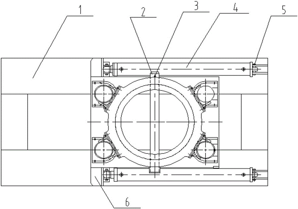
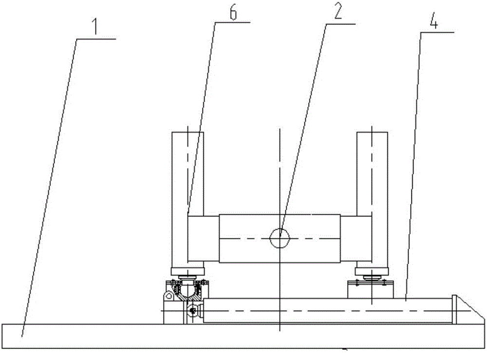
[0024] Such as Figure 1 to Figure 4 As shown in the figure, a device for ejecting and demoulding the locking pipe of the ground wall includes a locking pipe lifting and pushing bottom beam frame, a locking pipe ejecting device, and a horizontal pushing device.

[0025] The locking tube pulls and pushes the bottom beam frame 1. It is placed on a stable foundation and plays a supporting role. At the same time, the upper surface of the bottom beam frame is the sliding surface of the horizontal push of the device, and the maximum static friction force of the lower surface is greater than that of the upper surface. friction, so that the whole device can be placed stably.

[0026] The locking pipe jacking device includes a locking pipe jacking mach...


PUM


Abstract

The invention relates to a device applied to the pushing demoulding of a fore shaft pipe of a diaphragm wall. A bottom beam frame for pulling and pushing the fore shaft pipe is mounted on a stable foundation, and a fore shaft pipe puller is mounted on the bottom beam frame for pulling and pushing the fore shaft pipe. A shear pin assembly comprises a shear pin and a cotter pin, and the shear pin is mounted in a pin hole of a hold hoop and connects the fore shaft pipe and the fore shaft pipe puller. A moving oil cylinder base of a transverse pushing device is connected to a leg of the fore shaft pipe puller and is connected with an oil cylinder rod of a transverse pushing oil cylinder as a moving end through an oil cylinder connecting pin. A static oil cylinder base is connected with the bottom beam frame for pulling and pushing the fore shaft pipe and is connected with a cylinder sleeve of the transverse pushing oil cylinder as a static end through the oil cylinder connecting pin. In the invention, the problem of demoulding failure caused by demoulding force increase resulting from the tilting and deviation of the fore shaft pipe in a concrete pouring process and the problem of steel-edged rubber waterstop damage caused by pulling can be effectively solved; and demoulding accidents and the water seepage of the diaphragm wall, caused by waterstop damage are reduced.

Description

technical field [0001] The invention relates to a device for pushing and demoulding a locking pipe used in the construction of an underground continuous wall. Background technique [0002] At present, the underground diaphragm wall technology has been widely used throughout the country. The underground diaphragm wall has the characteristics of high structural rigidity, integrity, impermeability and durability, and can be used as a permanent soil retaining, water retaining and load-bearing structure; It can adapt to various complex construction environments and hydrogeological conditions. During the construction of the underground diaphragm wall, the part connecting two adjacent unit groove sections in the longitudinal direction of the wall is called the construction joint. Commonly used construction joints include circular lock pipe joints, I-shaped, Wang-shaped, cross, and V-shaped steel plate joints. When the lock pipe is used, grooves will be naturally formed on the sid...

Claims


Application Information

Patent Timeline
IPC IPC(8): E02D5/18E02D15/02
CPCE02D5/187E02D15/02
Inventor 李远青周铭谦朱德勇顾蓓瑛范斌
Owner SHANGHAI FOUND ENG GRP
Learn More