Construction method for static pressure carrier pile

A construction method and carrier pile technology, applied in sheet pile walls, infrastructure engineering, construction, etc., can solve problems such as increasing construction difficulty, reducing construction work efficiency, reducing work efficiency, etc., reducing the process of ramming and filling dry and hard concrete, and improving The bearing capacity of pile foundation and the effect of improving the strength of the carrier

Active Publication Date: 2016-09-07
王继忠
View PDF6 Cites 3 Cited by
  • Summary
  • Abstract
  • Description
  • Claims
  • Application Information

AI Technical Summary

Problems solved by technology

However, some problems have been found in the use of this patented technology, such as: ①A feature of this technology is that the heavy hammer is tamped out of the bottom of the casing for a certain distance before the filler is expanded, and it is required to hammer out the casing when the hammer is retracted The depth is greater than 50cm. Therefore, when the bearing layer at the pile end is an easily disturbed soil layer, the ramming method of hammering out the casing will cause a large disturbance to the bearing layer, so more fillers need to be rammed. In order to make the disturbed soil layer reach the required compactness, the disadvantages are that the material cost is increased, and the second is that the excessive amount of filler will cause damage to the adjacent piles and cause major quality problems.
②Because the particle size of the construction waste and other fillers used is relatively large, it is necessary to lift the weight out of the upper opening of the casing every time the filler is filled to complete the filler. The energy is high, which increases the disturbance to the bearing layer at the pile end. The second is that it takes a long time to raise the heavy hammer every time, and the process is slow, which greatly reduces the construction efficiency.
③Because the gap between the heavy hammer and the casing is small, its disadvantages are that there is no exhaust channel around the heavy hammer when it is rammed, which will generate air support at the bottom of the hammer, which will affect the hammering energy, and the second is that after the heavy hammer rams out of the casing When it is lifted again, it is still affected by the lack of exhaust channels, and a negative pressure zone will be generated between the bottom of the hammer and the soil, which not only increases the energy required to lift the hammer, but the existence of the vacuum negative pressure zone will also aggravate the formation of groundwater. Resurgence increases construction difficulty and reduces work efficiency
④ Most of the construction waste and other fillers used are demolition bricks or even new bricks. The disadvantages are that clay bricks are used less and less with the development of construction, so that the cost of ramming fillers continues to increase. Second, it is easy to cause construction waste. Secondary pollution
⑤ This technology also includes the process of tamping dry hard concrete, but during the hammer tamping process, the stones in the dry hard concrete are basically rammed into powder by the heavy hammer, which greatly reduces the strength of the dry hard concrete
However, the static pressure pile machine is generally used for the construction of prefabricated piles, and the scope of application is small, and the piles constructed by the static pressure method are mostly friction piles, and the bearing capacity is limited.

Method used


Image

  • Construction method for static pressure carrier pile
  • Construction method for static pressure carrier pile

Examples


Embodiment Construction

[0032] The present invention will be further described below by specific examples.

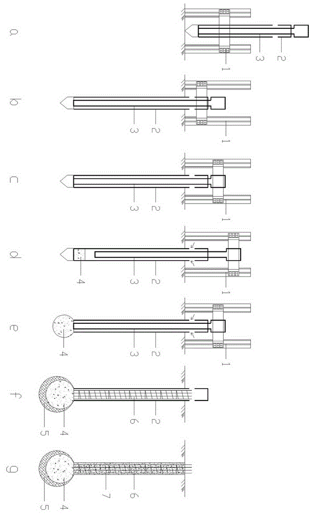
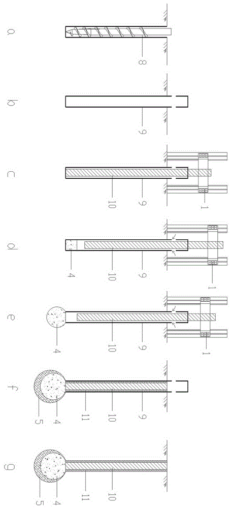
[0033] figure 1 It is a process diagram of an embodiment of the static pressure carrier pile construction method of the present invention, at first, as figure 1 As shown in middle a, the clamping system 1 of the static pressure pile machine holds the outer pipe 2, and the inner pipe 3 is nested in the outer pipe 2, and the diameter of the upper part of the inner pipe 3 is thickened and equal to the outer diameter of the outer pipe 2; then ,Such as figure 1 As shown in middle b, a prefabricated pile tip is placed at the bottom of the outer pipe 2, and the outer pipe 2 is statically pressed into the soil to the design depth; then, as figure 1 As shown in middle c, loosen and move up the clamping system 1 to hold the inner tube 3; then, as figure 1 As shown in middle d, the clamp inner tube 3 is raised to a certain height, and the filler opening at the upper end of the outer tube 2 is filled w...


PUM


Abstract

The invention provides a construction method for a static pressure carrier pile. The construction method for the static pressure carrier pile includes the steps that firstly, an outer pipe is clasped by a clamping system of a static pile driver, and an inner pipe is sleeved with the outer pipe in an overlapped manner; secondly, the outer pipe is pressed by the designed depth in a static pressing manner; thirdly, the inner pipe is clasped by the clamping system; fourthly, the inner pipe is lifted up, a gap between the inner pipe and the outer pipe is filled with a fine particle packing material, the inner pipe is clasped, and the packing material is pressed downwards; fifthly, downward-pressing operation of the packing material is repeated till a carrier is formed at the bottom end of the pile, and the tip resistance pressure numerical value is observed; and sixthly, a cast-in-situ or embedded concrete pile body is manufactured. The other construction method for the static pressure carrier pipe includes the steps that firstly, sinking of a pile casing is conducted; secondly, a prefabricated pile body is clasped by the clamping system of the static pile driver and is sunk into the pile casing; thirdly, the prefabricated pile body is lifted up, a gap between the pile casing and the prefabricated pile body is filled with the fine particle packing material, the prefabricated pile body is clasped, and the packing material is pressed downwards; fourthly, downward-pressing operation of the packing material is repeated till the carrier is formed at the bottom end of the pile, and the tip resistance pressure numerical value is observed; and fifthly, the gap between the pile casing and the prefabricated pile body is filled with cement mortar, the pile casing is lifted out, and the pile is formed.

Description

technical field [0001] The invention relates to a pile foundation construction technology, in particular to a construction method of a static pressure carrier pile. Background technique [0002] A construction technology of concrete piles is disclosed in the patent No. ZL98101041.5, which is characterized in that an artificial bearing layer is formed by performing operations such as filling and compacting at the bottom of the pile, so that the upper load passes through the concrete pile body and the pile. The artificial bearing layer at the bottom is transferred to the better bearing layer, thereby improving the bearing capacity of the pile. However, some problems have been found in the use of this patented technology, such as: ①A feature of this technology is that the heavy hammer is tamped out of the bottom of the casing for a certain distance before the filler is expanded, and it is required to hammer out the casing when the hammer is retracted The depth is greater than ...

Claims


Application Information

Patent Timeline
Patent Type & Authority Applications(China)
IPC IPC(8): E02D7/20E02D5/44
CPCE02D5/385E02D5/44E02D7/20E02D2300/0018
Inventor 王继忠
Owner 王继忠
Why Eureka
Try Eureka