Eureka AIR delivers breakthrough ideas for toughest innovation challenges, trusted by R&D personnel around the world.

Swing-resistant electromagnetic hybrid active actuation mechanism

An electromagnetic hybrid and actuator technology, applied in the direction of electromagnets, electromagnets with armatures, mechanical equipment, etc., can solve problems such as less consideration of anti-sway performance, achieve simple and reliable installation methods, avoid stagnation, and increase magnetic field strength Effect

Inactive Publication Date: 2016-09-07
NO 719 RES INST CHINA SHIPBUILDING IND
View PDF7 Cites 7 Cited by
  • Summary
  • Abstract
  • Description
  • Claims
  • Application Information

AI Technical Summary

Problems solved by technology

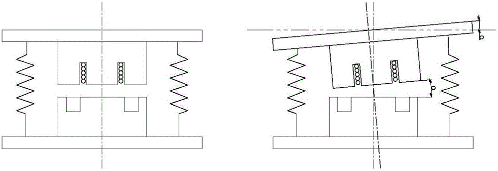
For large-scale underwater combat weapons, there are tilting and swaying operating states. At present, active actuators in conventional designs have less consideration for anti-swaying performance. In order to speed up the application of active control technology for large-scale underwater combat weapons, it is necessary to combine Anti-swing performance design of active actuator

Method used


Image

  • Swing-resistant electromagnetic hybrid active actuation mechanism
  • Swing-resistant electromagnetic hybrid active actuation mechanism
  • Swing-resistant electromagnetic hybrid active actuation mechanism

Examples


Embodiment Construction

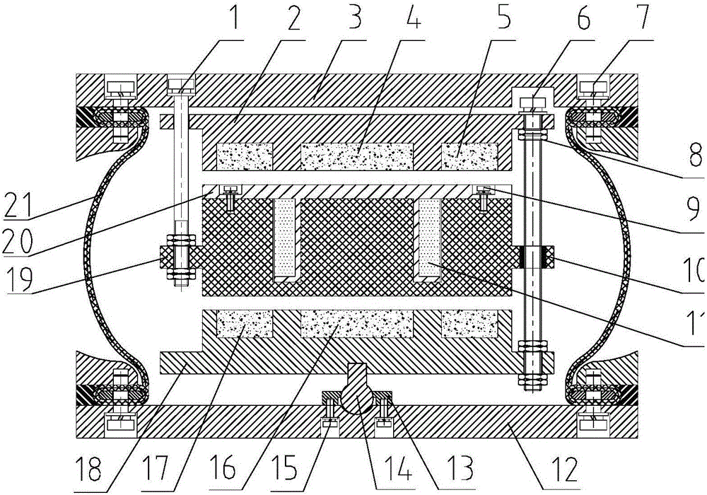
[0020] Refer to the attached drawings, an anti-sway electromagnetic hybrid actuator, which includes: middle screw 1, upper armature 2, upper cover plate 3, upper circular permanent magnet 4, upper annular permanent magnet 5, fixed screw 6, shell Locking bolt 7, locking nut 8, coil cage fixing bolt 9, linear bearing 10, coil winding 11, lower cover 12, ball head cover 13, ball head shaft 14, ball head shaft fixing bolt 15, lower circle Shaped permanent magnet 16, lower annular permanent magnet 17, lower armature 18, middle armature 19, coil holder 20 and airbag shock absorber body 21;

[0021] The overall structure from top to bottom is: upper cover 3, upper armature 2, coil holder 20, middle armature 19, lower armature 18 and lower cover 12;

[0022] The upper circular permanent magnet 4 and the upper annular permanent magnet 5 are respectively embedded in the central groove of the lower end surface of the upper armature 2 and the annular groove coaxial with the central groove;

[0...


PUM


Abstract

The invention belongs to the technical field of vibration noise control, and particularly relates to a vibration active control technology. According to the technical scheme of a swing-resistant electromagnetic hybrid active actuation mechanism, a passive vibration isolator is composed of an upper cover plate, an airbag damper bag body, a lower cover plate and shell locking bolts and is used for suppressing medium-high frequency vibration of a controlled object; an active actuation mechanism body is composed of an upper armature, a middle armature, a lower armature, circular permanent magnets, annular permanent magnets, coil windings, a coil retainer, a middle screw, a fixing screw and a linear bearing; The permanent magnets and the armatures form a magnetic channel; current coils cut magnetic lines of force in the magnetic channel to generate electromagnetic force; and the distance between the upper permanent magnet and the coil windings is equal to the distance between the lower permanent magnet and the coil windings, so that it is ensured that the average magnetic field strength in the coils of the middle armature driven by the electromagnetic force is consistent, the magnitude of output force does not change with changes of strokes of the middle armature, and nonlinearity is avoided. It is ensured that the output force of the active actuation mechanism is normal when controlled equipment inclines or swings, and the stuck stagnation phenomenon of a conventional actuation mechanism is avoided.

Description

Technical field [0001] The invention belongs to the technical field of vibration and noise control, and particularly relates to vibration active control technology. Background technique [0002] Vibration and noise reduction is currently receiving extensive attention and attention. For the prominent low-frequency line spectrum of rotating power equipment, the current suppression measures include passive dynamic vibration absorption and active vibration isolation. Passive vibration absorption can only be better for a single constant frequency. Inhibition effect. In practice, the frequency of the equipment often drifts or the equipment has a frequency conversion function, which causes the frequency to change with different operating conditions. At this time, passive vibration absorption is no longer applicable. For equipment with multi-line spectra and frequency changes, active vibration control technology has good adaptability. Active control can adaptively track changes in freque...

Claims


Application Information

Patent Timeline
Patent Type & Authority Applications(China)
IPC IPC(8): F16F15/023F16C11/06H01F7/13
CPCF16C11/0623F16F15/0232H01F7/13
Inventor 刘记心余永丰李强周刘彬马玺越强磊陶襄樊朱海雄
Owner NO 719 RES INST CHINA SHIPBUILDING IND
Why Eureka
Eureka Blog
Learn More