Supercharge Your Innovation With Domain-Expert AI Agents!

Multi-core processor system, allocation program, control program, allocation method, and control method

A technology of multi-core processor and control method, applied in the direction of program control design, multi-program device, resource allocation, etc., can solve the problem of load concentration and achieve the effect of low power consumption

Inactive Publication Date: 2016-09-07
FUJITSU LTD
View PDF8 Cites 2 Cited by
  • Summary
  • Abstract
  • Description
  • Claims
  • Application Information

AI Technical Summary

Problems solved by technology

However, when multiple processes are started in the process-dedicated CPU and no driver is executed by the driver-dedicated CPU, there is a problem that the load is concentrated only on the process-dedicated CPU.

Method used


Image

  • Multi-core processor system, allocation program, control program, allocation method, and control method
  • Multi-core processor system, allocation program, control program, allocation method, and control method
  • Multi-core processor system, allocation program, control program, allocation method, and control method

Examples


Embodiment approach 1

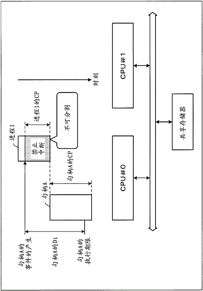
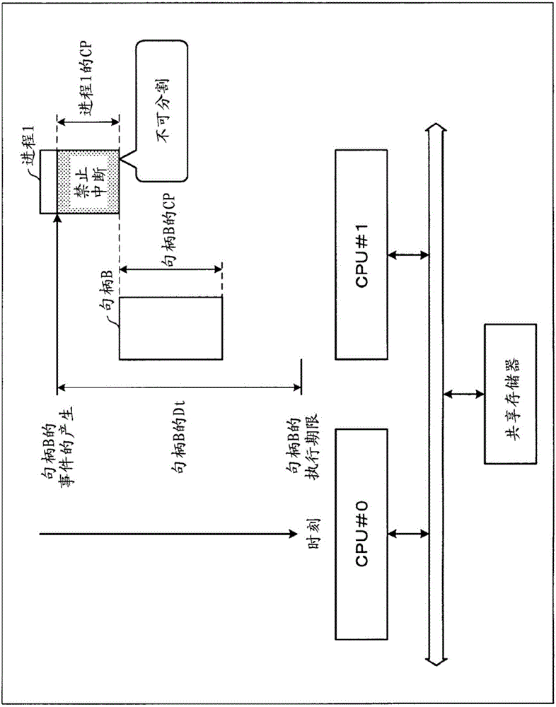
[0050] In Embodiment 1, the calculation of the execution time of each driver will be described using the ESL (Electronic System Level) model. Here, the ESL model refers to a technique for simulating a hardware environment by describing based on the behavior (behavior) of a hardware device. For example, in the ESL model of the CPU, the mechanism of the electrical circuit for issuing commands is not simulated as it is, but is represented by issuing commands and the time required for them.

[0051] In addition, in the ESL model of the bus, the circuit mechanism is not used to strictly calculate the delay of data propagation, but the latent mode of the design is multiplied according to the access requirements, and the concept of action and time is used as behavior (action) to simulate.

[0052] Conventionally, simulation refers to performing simulation without actually mounting semiconductors based on circuit design information such as RTL (Register Transfer Level), and is used fo...

Embodiment approach 2

[0085] Next, in Embodiment 2, distribution of drivers and distribution of applications will be described. Here, in a multi-core processor system, a multi-core processor refers to a processor equipped with a plurality of cores. As long as it is equipped with multiple cores, it may be a single processor equipped with multiple cores, or a processor group in which single-core processors are paralleled. In this embodiment, in order to simplify the description, a processor group in which single-core processors are arranged in parallel is used as an example for description.

[0086] (hardware for multi-core processor systems)

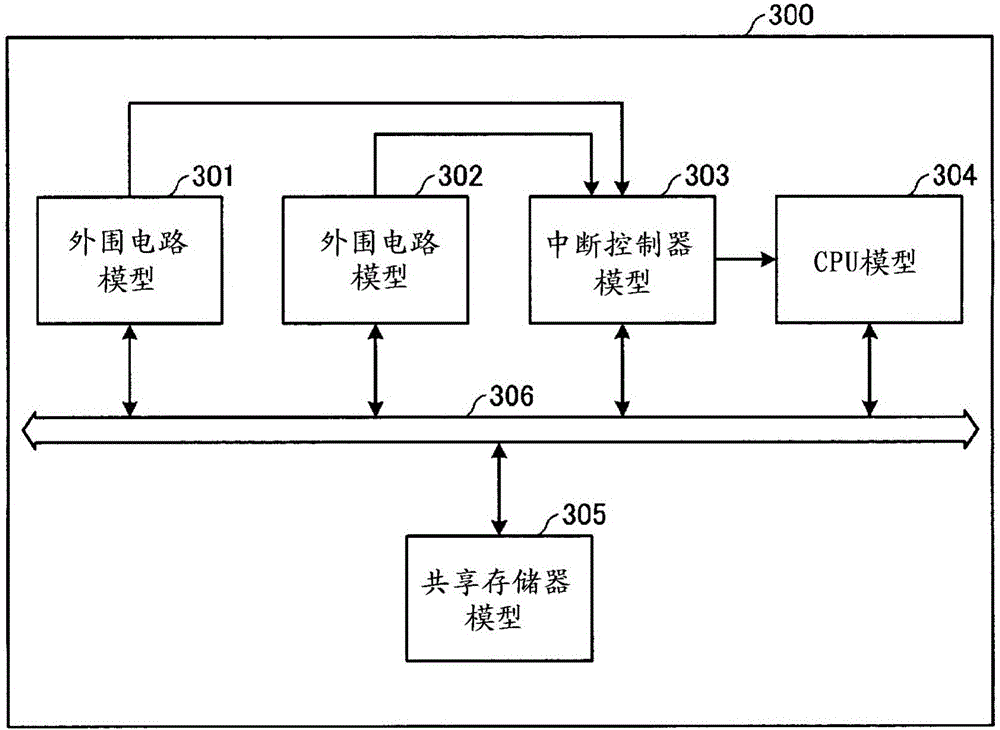
[0087] Figure 9 is a block diagram representing the hardware of a multi-core processor system. The multi-core processor system 900 includes a peripheral circuit 901 , a peripheral circuit 902 , an interrupt controller 903 , CPU#0 , CPU#1 , a shared memory 905 , and a clock supply circuit 906 . Each part is connected by the bus 904 .

[0088] CPU#0 and CP...


PUM


Abstract

A CPU#0 detects an allocation instruction of a process 1. The CPU#0 obtains residual time, wherein the residual time is time obtained by subtracting time (Dt of a handle) from a generation moment of an event of the handle B, which is allocated to a CPU#1 and that is interrupted, to an execution deadline of the handle B by processing time of a handle A (i.e. CP of the handle B). The CPU#0 determines whether the obtained residual time is over processing time (CP of a process 1) of processing which is defined as interrupt disability of the process 1. That is, when the process 1 is allocated to the CPU#1, even if the event of the handle B is generated during execution of the process 1, whether the Dt of the handle B can be complied with is determined. If the event of the handle B is generated during execution of the process 1, it is determined that the Dt of the handle B can be complied with. Therefore, the CPU#0 allocates the process 1 to the CPU#1.

Description

[0001] This application is a divisional case of an invention patent application with the national application number 201080068231.6, the date of entering the Chinese national phase is January 24, 2013, and the invention title is "multi-core processor system, distribution program, control program, distribution method and control method" Application. technical field [0002] The invention relates to a multi-core processor system, an allocation program and an allocation method for controlling process allocation or driver program allocation. Furthermore, the present invention relates to a multi-core processor system, a control program, and a control method that control the frequency of a clock supplied to a processor. Background technique [0003] Conventionally, there is known a technology in which a process corresponding to a device is processed at high speed by withdrawing a process currently being executed by a CPU (Central Processing Unit) in response to an interrupt signal...

Claims


Application Information

Patent Timeline
Patent Type & Authority Applications(China)
IPC IPC(8): G06F13/24G06F1/32G06F9/48G06F9/50G06F13/26G06F13/34
CPCG06F13/24G06F1/324G06F1/329G06F9/4812G06F9/5033G06F13/26G06F13/34
Inventor 山下浩一郎铃木贵久山内宏真栗原康志
Owner FUJITSU LTD
Features
  • R&D
  • Intellectual Property
  • Life Sciences
  • Materials
  • Tech Scout
  • Unparalleled Data Quality
  • Higher Quality Content
  • 60% Fewer Hallucinations
Learn More