Check patentability & draft patents in minutes with Patsnap Eureka AI!

Permanent magnet structure with constant gradient

A permanent magnet and gradient technology, applied in the direction of magnets, permanent magnets, magnetic objects, etc., to achieve the effect of reducing the amount of permanent magnets, reducing the weight of magnets, and reducing the cost of use and maintenance.

Active Publication Date: 2016-09-07
SHENZHEN ACAD OF AEROSPACE TECH
View PDF5 Cites 2 Cited by
  • Summary
  • Abstract
  • Description
  • Claims
  • Application Information

AI Technical Summary

Problems solved by technology

Although this reduces MRI resolution, such reduction is acceptable

Method used


Image

  • Permanent magnet structure with constant gradient
  • Permanent magnet structure with constant gradient

Examples


Embodiment Construction

[0016] The preferred embodiments of the present invention will be described in detail below with reference to the accompanying drawings. It should be understood that the preferred embodiments are only for illustrating the present invention, not for limiting the protection scope of the present invention.

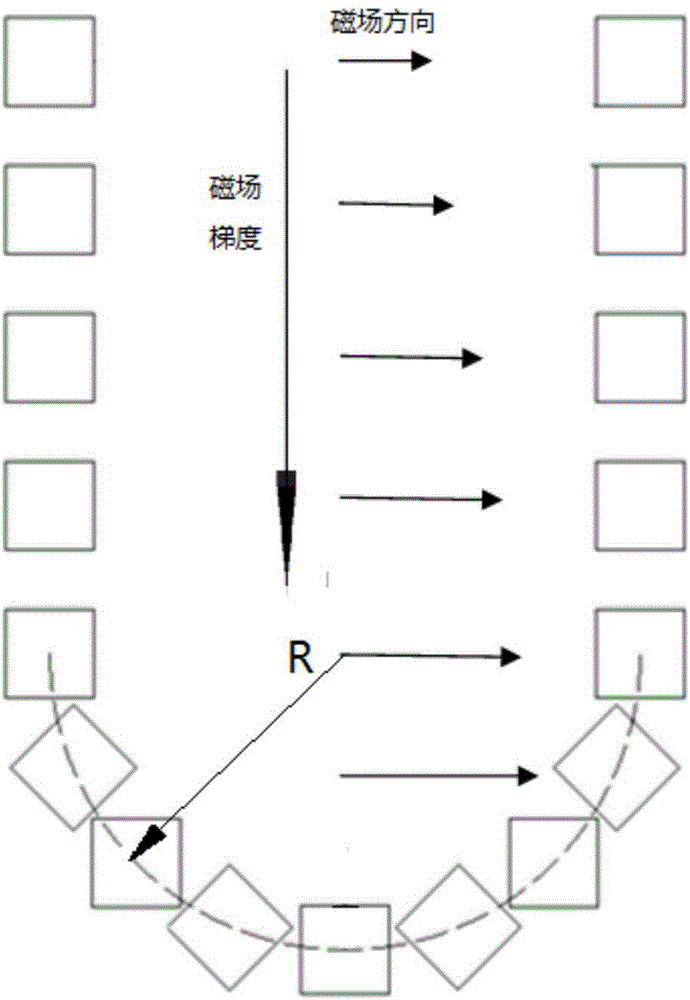
[0017] figure 1 It is the layout diagram of the present invention, which is composed of a plurality of U-shaped discretely arranged permanent magnet units that can generate a static magnetic field with a constant gradient in the U-shaped central area. The constant gradient refers to the magnetic field strength of the static magnetic field to the U-shaped central area. Shows a certain gradient change, the specific structure:

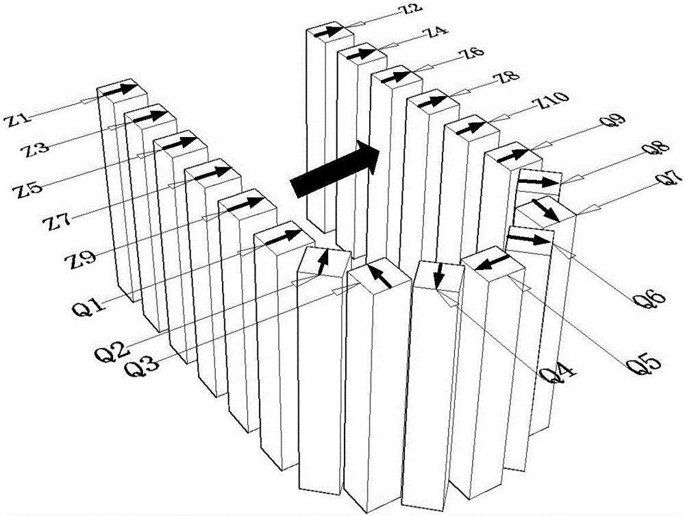
[0018] It is composed of two rows of permanent magnet units arranged in parallel and equidistantly and a permanent magnet structure arranged in a semi-circular shape. The two rows of the double-row permanent magnet unit are arranged equidistantly by Z perman...


PUM


Abstract

The invention discloses a permanent magnet structure with a constant gradient, and belongs to the field of a non-destructive testing technology. The permanent magnet structure comprises multiple permanent magnet units which are in U-shaped discrete distribution and capable of generating a static magnetic field with a constant gradient in a U-shaped central region. According to the permanent magnet structure provided by the invention, the permanent magnet structure is formed by the discrete rod-shaped permanent magnets, so that the usage amount and the weight of the permanent magnets can be effectively reduced; meanwhile, the static magnetic field with the constant gradient is generated in the central region by the structure; and when the permanent magnet structure is used for nuclear magnetic resonance imaging, a path of gradient system can be omitted, so that the use cost and the maintenance charge of the equipment can be further lowered.

Description

Technical field [0001] The invention belongs to the technical field of non-destructive testing, and specifically relates to a permanent magnet structure with a constant gradient for a lightweight open nuclear magnetic resonance imaging device. Background technique [0002] As a non-destructive testing method, nuclear magnetic resonance technology is widely used in life medicine, food analysis, quality control, materials science and geophysics. The existing nuclear magnetic resonance imaging equipment has the advantages of high field strength, high resolution, and high imaging accuracy, but its purchase and maintenance costs are high, and the purchase cost is as high as one million US dollars per Tesla, resulting in high usage costs; and its size It is large and heavy, and its mobility is seriously insufficient. It is difficult to apply to some places that need on-site inspection or monitoring (such as the scene of traffic accidents), which restricts its wider application. [0003]...

Claims


Application Information

Patent Timeline
IPC IPC(8): H01F7/02
CPCH01F7/021
Inventor 贺玉成何为徐征
Owner SHENZHEN ACAD OF AEROSPACE TECH
Features
  • R&D
  • Intellectual Property
  • Life Sciences
  • Materials
  • Tech Scout
  • Unparalleled Data Quality
  • Higher Quality Content
  • 60% Fewer Hallucinations
Learn More