Method for detecting position of rotor of electrically excited synchronous motor without sensor in whole process based on excitation current pulse response

A technology of excitation current and synchronous motors, applied in the direction of electronically commutated motor control, electrical components, control systems, etc., can solve the problems of high-frequency signal limitation, achieve the effect of small interference, improve reliability, and improve the starting effect

Active Publication Date: 2016-09-07
HARBIN INST OF TECH
View PDF4 Cites 2 Cited by
  • Summary
  • Abstract
  • Description
  • Claims
  • Application Information

AI Technical Summary

Problems solved by technology

[0005] The purpose of the present invention is to solve the problem that the high-frequency signal injected from the stator side is limited in the control method of the frequency conversion device, and to provide a sensorless detection method for the rotor position of an electrically excited synchronous motor based on the excitation current pulsation response.

Method used


Image

  • Method for detecting position of rotor of electrically excited synchronous motor without sensor in whole process based on excitation current pulse response
  • Method for detecting position of rotor of electrically excited synchronous motor without sensor in whole process based on excitation current pulse response
  • Method for detecting position of rotor of electrically excited synchronous motor without sensor in whole process based on excitation current pulse response

Examples


specific Embodiment approach 1

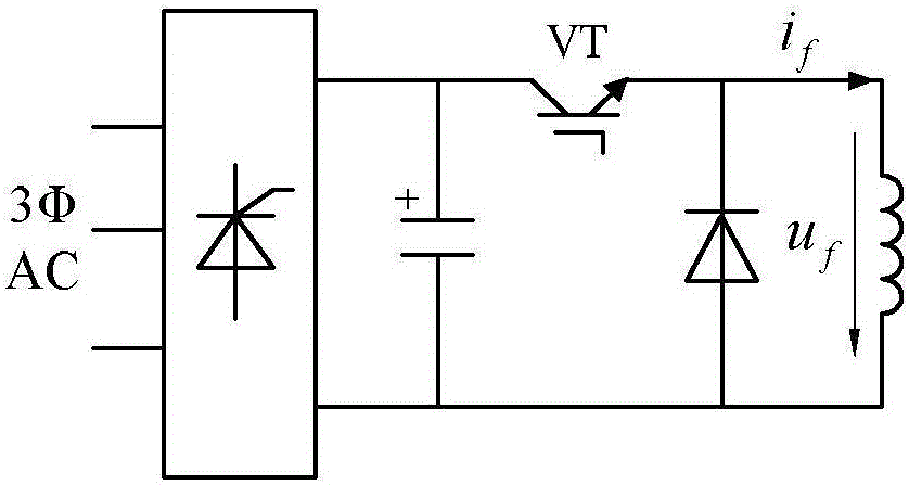
[0024] Specific implementation mode one: the following combination Figure 1 to Figure 10 Describe this embodiment, the method for detecting the rotor position of an electrically excited synchronous motor based on the excitation current pulsation response in this embodiment without a sensor throughout the whole process, the method includes the following steps:

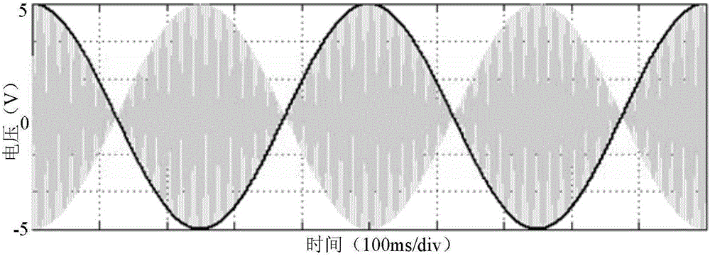
[0025] Step 1: Adopt an appropriate trigger strategy of the excitation bridge circuit to make the excitation current superimpose a fixed frequency pulsating signal on the basis of the DC component, and the fixed frequency of the pulsating signal is f h .

[0026] At this time, the expression of excitation current is:

[0027]

[0028] where I f is the excitation current i f effective value; I h is the amplitude of the high-frequency component of the excitation current; ωk is the angular frequency of the high-frequency component of the excitation current; is the phase of the high frequency component of the exci...


PUM


Abstract

The invention relates to a method for detecting the position of a rotor of an electrically excited synchronous motor without a sensor in a whole process based on excitation current pulse response, belonging to the field of control of motors. The problem that injection of a high-frequency signal from a stator side is limited by a frequency converter control method can be solved. The method disclosed by the invention comprises the following steps of: (1), adopting a triggering strategy of an excitation bridge circuit, such that a pulse signal having a fixed frequency is superposed on excitation current on the basis of a direct-current component, wherein the fixed frequency of the pulse signal is fh; (2), acquiring three-phase counter electromotive force line voltage of the motor, and extracting the pulse signal, the frequency of which is fh; (3), extracting envelope lines eAB_h, eBC_h and eCA_h of three-phase high-frequency signal induced electromotive force of the pulse signal, the frequency of which is fh; and (4), calculating the mechanical angle of the rotor of the synchronous motor according to the three-phase envelope lines extracted in the step (3).

Description

technical field [0001] The invention belongs to the field of motor control. Background technique [0002] In recent years, the continuous development of electric power transmission system has made synchronous motors more widely used. Compared with asynchronous motors, synchronous motors have many advantages such as high and adjustable power factor, small inverter capacity, and high control precision. However, the synchronous motor is different from other motors in that it must be able to detect the rotor position of the motor in real time during the start-up period, and use this as a basis to control the operation of the synchronous motor. However, the traditional mechanical position sensor is cumbersome to install, the detection accuracy is greatly affected by the environment, and the work reliability is low. Therefore, researchers have been working on sensorless rotor position detection methods. [0003] At present, the rotor position detection method of synchronous mot...

Claims


Application Information

Patent Timeline
Patent Type & Authority Applications(China)
IPC IPC(8): H02P6/182
CPCH02P6/182
Inventor 高强寇佳宝徐殿国韩啸李文爽张婉莹
Owner HARBIN INST OF TECH
Why Eureka
Try Eureka