Resistance voltage divider type DAC-PUF circuit

A resistance divider and resistance technology, applied in logic circuits, electrical components, digital-to-analog converters, etc., can solve the problems of large resistance deviation range and deviation of actual resistance value from theoretical value, etc.

Active Publication Date: 2016-09-07
NINGBO UNIV
View PDF3 Cites 12 Cited by
  • Summary
  • Abstract
  • Description
  • Claims
  • Application Information

AI Technical Summary

Problems solved by technology

In the standard CMOS process, diffusion regions, well regions, and polysilicon can all be used to make resistors. However, due to factors such as resistor edge effects, electron mobility, and random changes in resistor thickness, the actual resistance value deviates from the theoretical value, and the geometric size of the resistor is smaller. The smaller the resistance value, the larger the deviation range

Method used


Image

  • Resistance voltage divider type DAC-PUF circuit
  • Resistance voltage divider type DAC-PUF circuit
  • Resistance voltage divider type DAC-PUF circuit

Examples


Embodiment 1

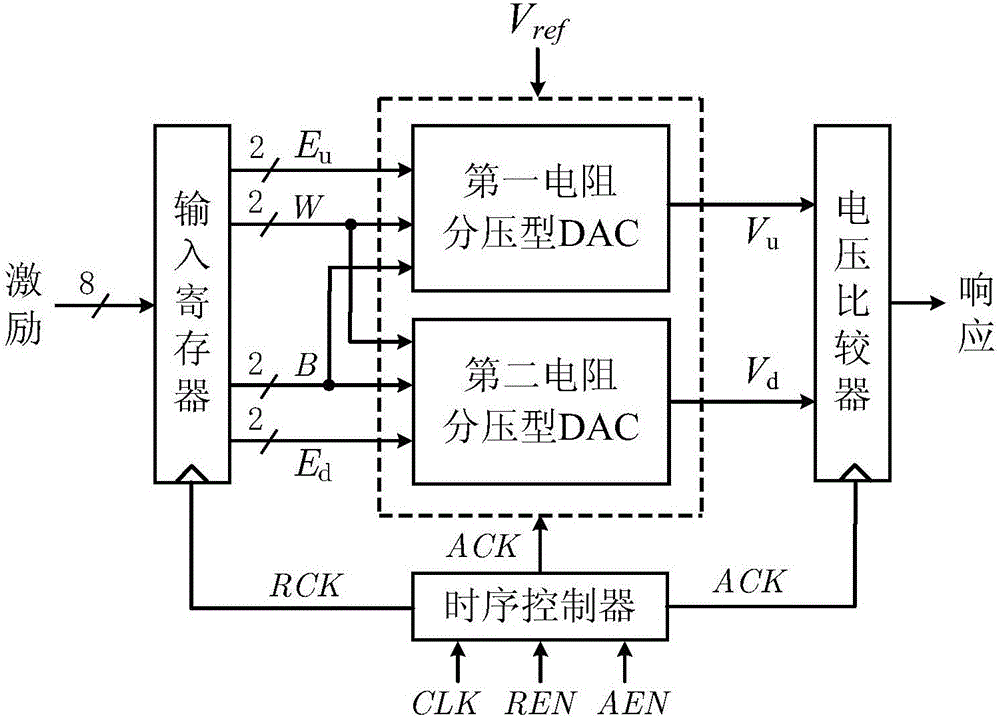
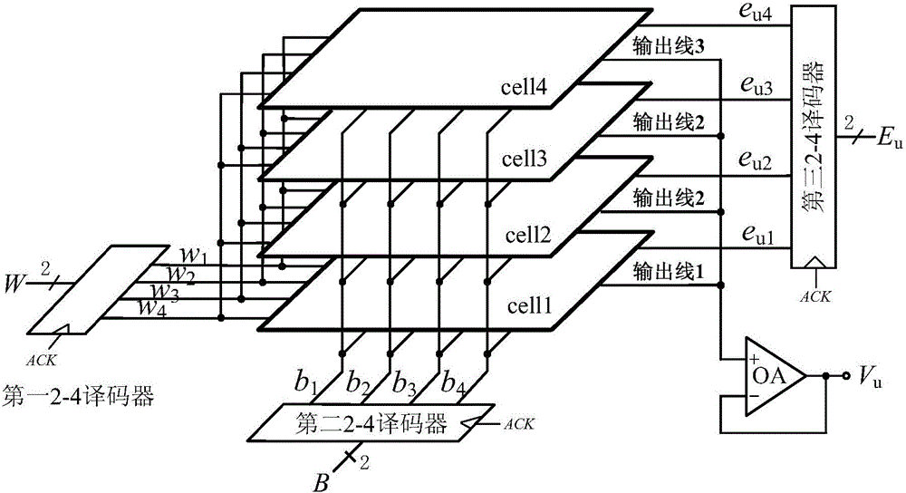
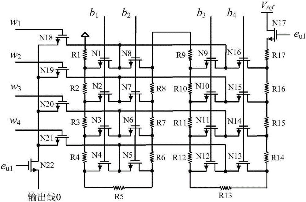
[0022] Embodiment one: if Figure 1 ~ Figure 3As shown, a resistor divider DAC-PUF circuit includes an input register, an offset voltage generating circuit, a voltage comparator and a timing controller. The input register has a clock terminal, an input terminal, a first output terminal, a second output terminal, The third output terminal and the fourth output terminal, the voltage comparator has a clock terminal, a first input terminal, a second input terminal and an output terminal, the timing controller is respectively connected to the clock terminal of the input register and the clock terminal of the voltage comparator, and the deviation The voltage generating circuit includes two resistor divider DACs with the same structure, and the resistor divider DAC includes three 2-4 decoders with the same structure, operational amplifiers and four resistor divider units with the same structure, and the 2-4 translator The coder has a clock terminal, an input terminal, a first output ...

Embodiment 2

[0023] Embodiment two: if Figure 1 ~ Figure 3As shown, a resistor divider DAC-PUF circuit includes an input register, an offset voltage generating circuit, a voltage comparator and a timing controller. The input register has a clock terminal, an input terminal, a first output terminal, a second output terminal, The third output terminal and the fourth output terminal, the voltage comparator has a clock terminal, a first input terminal, a second input terminal and an output terminal, the timing controller is respectively connected to the clock terminal of the input register and the clock terminal of the voltage comparator, and the deviation The voltage generating circuit includes two resistor divider DACs with the same structure, and the resistor divider DAC includes three 2-4 decoders with the same structure, operational amplifiers and four resistor divider units with the same structure, and the 2-4 translator The coder has a clock terminal, an input terminal, a first output ...


PUM


Abstract

The present invention discloses a resistance voltage divider type DAC-PUF circuit which comprises an input register, a bias voltage generation circuit, a voltage comparator, and a time sequence controller. The bias voltage generation circuit comprises a two resistance voltage divider type DACs with the same structure. Each of the resistance voltage divider type DACs comprises three 2-4 decoded with the same structure, an operational amplifier, and four resistance divider units with the same structure. The resistance divider units comprise 22 NMOS tubes and 17 resistors. The circuit has the advantages that a digital and analog mixing mode is employed, the mismatch of the resistance voltage divider type DAC resistors is used to generate a bias voltage signal, the output key change is realized, in the TSMC-LP 65nm CMOS process, a full customization mode is used to design the circuit layout of the invention, the resistance voltage divider type DAC-PUF circuit is tested, an experimental result shows that the uniqueness of the resistance voltage divider type DAC-PUF circuit is strong, the randomness and reliability in different working environments are larger than 99.1% and 97.8%, and the circuit can be widely applied to the fields of key generation and device authentication.

Description

technical field [0001] The invention relates to a PUF circuit, in particular to a resistance voltage dividing DAC-PUF circuit. Background technique [0002] With the rapid development of information technology, people pay more and more attention to information security. The physical unclonable function (Physical Unclonable Function, PUF) circuit provides a way to enhance information security from the hardware texture characteristics. The concept of PUF was first proposed by Pappu and other researchers. It is a "DNA feature recognition technology" in the field of integrated circuits. At present, the silicon-based PUF circuit is the most important research direction. It utilizes the slight process deviation between the unit circuits with the same structure and design parameters (expressed in the electrical characteristics as voltage, current, delay, etc.) to generate Responses that are unique, random, and unclonable. Uniqueness means that a given PUF circuit has a unique fun...

Claims


Application Information

Patent Timeline
Patent Type & Authority Applications(China)
IPC IPC(8): H03K19/094H03M1/66
CPCH03K19/094H03M1/66
Inventor 李刚汪鹏君陈伟伟张跃军
Owner NINGBO UNIV
Why Eureka
Try Eureka