A linear reciprocating yarn guide device driven by magnetic force and its application method

A technology of linear reciprocating and yarn guiding device, which is applied in the directions of transportation and packaging, transportation of filamentous materials, processing of thin materials, etc. and other problems, to achieve the effects of high precision control, avoidance of internal friction, and low internal friction

Inactive Publication Date: 2018-08-31
WUHAN TEXTILE UNIV
View PDF10 Cites 0 Cited by
  • Summary
  • Abstract
  • Description
  • Claims
  • Application Information

AI Technical Summary

Problems solved by technology

[0004] In this design, the yarn guide device that drives the yarn guide rod belongs to the mechanical structure driven by the motor. During the process of driving the mechanical structure to reciprocate, there will be a large mutual friction between the parts inside the mechanical structure. This kind of friction is not only It will affect the normal reciprocating motion of the yarn guide rod, and will consume additional energy, increasing the energy consumption of the overall equipment

Method used


Image

  • A linear reciprocating yarn guide device driven by magnetic force and its application method
  • A linear reciprocating yarn guide device driven by magnetic force and its application method
  • A linear reciprocating yarn guide device driven by magnetic force and its application method

Examples


Embodiment 1

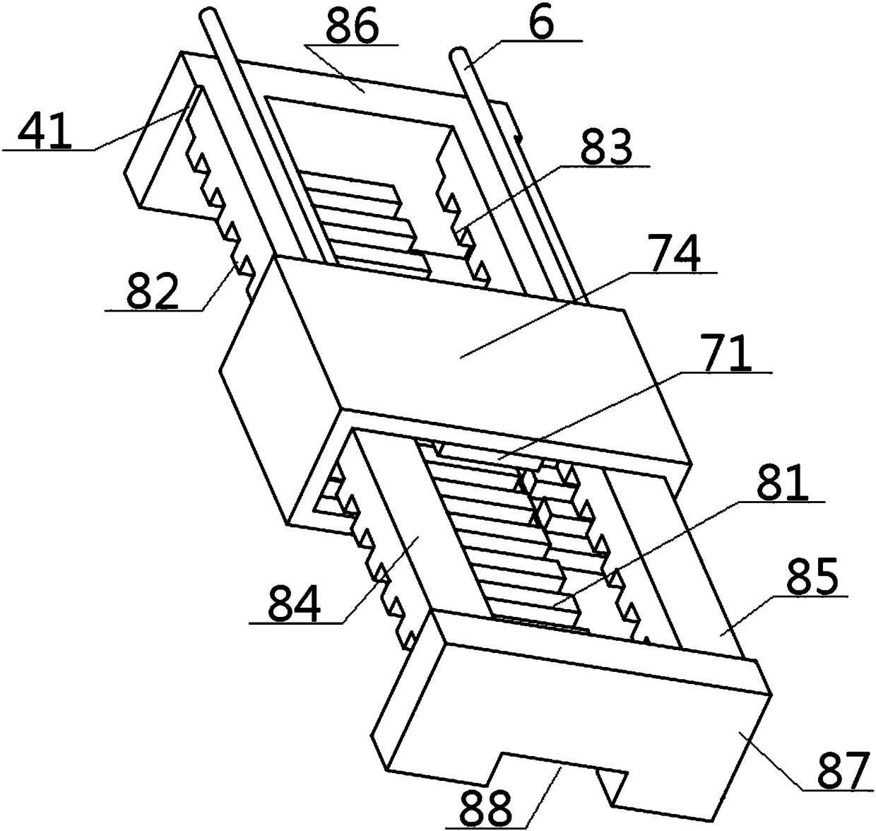
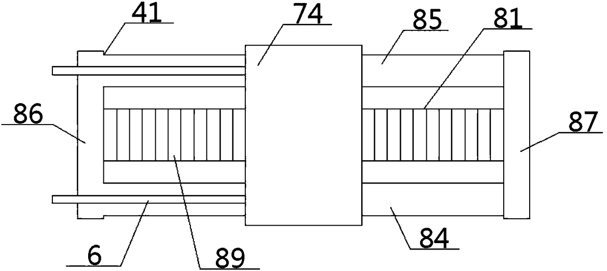
[0051] see Figure 1 to Figure 6 , a linear reciprocating yarn guide device driven by magnetic force, comprising a friction roller 1, a yarn reel 2 and a yarn guide system 4, the top surface of the friction roller 1 is in contact with the bottom surface of the yarn reel 2, the friction roller 1, The yarn bobbin 2 is frictionally driven and matched, the circumferential surface of the yarn bobbin 2 is wound with the yarn 3, the other end of the yarn 3 is connected with one end of the yarn guide rod 6 after passing through the yarn guide nozzle 5, and the other end of the yarn guide rod 6 It is connected with the front plate surface of the slider top plate 74 in the yarn guide system 4; the yarn guide system 4 includes a slider unit 7 and a slide rail unit 8 passing through it, and the slider unit 7 and the slide rail unit 8 are in the Sliding fit on a straight line;

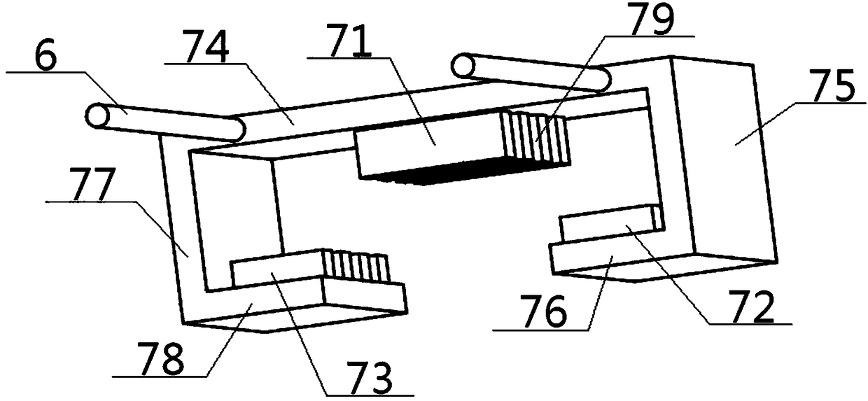
[0052] The slider unit 7 includes a top thrust winding 71, a left suspension winding 72, a right suspension win...

Embodiment 2

[0057] Basic content is the same as embodiment 1, the difference is:

[0058]Under the action of the thrust, the slider top plate 74 runs linearly along the initial direction to the predetermined position, then changes the direction of the three-phase current to change the direction of the thrust force, so that the slider top plate 74 returns along the original route, and cycles in turn to realize the slider top plate 74 reciprocating motion in a linear direction.

Embodiment 3

[0060] Basic content is the same as embodiment 1, the difference is:

[0061] The slider unit 7 also includes a left vertical plate 75, a left supporting plate 76, a right vertical plate 77 and a right supporting plate 78, the top of the left vertical plate 75 is vertically connected with the left end of the slider top plate 74, and the left vertical plate 75 The bottom of the bottom is vertically connected with the outer end of the left supporting plate 76, the inner end of the left supporting plate 76 and the inner end of the right supporting plate 78 are directly arranged, the outer end of the right supporting plate 78 is vertically connected with the bottom of the right vertical plate 77, and the right vertical plate 77 is vertically connected. The top of the plate 77 is vertically connected with the right end of the slider top plate 74, the top thrust winding 71 is located between the inner end of the left supporting plate 76 and the inner end of the right supporting plate...


PUM


Abstract

The invention discloses a magnetic-driven linear reciprocating yarn guide device. The device comprises a friction roller, a bobbin and a yarn guide system, wherein the yarn guide system includes a slide block unit and a slide rail unit slidingly matched with each other; the slide block unit includes a top thrust winding, a left suspension winding, a right suspension winding and a slide block top plate; the slide rail unit includes a middle thrust permanent magnet, a left suspension permanent magnet, a right suspension permanent magnet, a left slide rail and a right slide rail; in operation, the other end of a yarn wound on the bobbin is connected with a front surface of the slide block top plate after passing through a yarn guide nozzle and a yarn guide rod in sequence; the left suspension winding, the right suspension winding, the left suspension permanent magnet and the right suspension permanent magnet correspondingly generate magnetic cooperation to suspend the left slide rail and the right slide rail; and meanwhile, the top thrust winding and the middle thrust permanent magnet generate magnetic cooperation to push the slide block top plate to perform a linear reciprocating motion. The device is lower in internal friction force, lower in energy consumption, higher in control precision, simple in structure and easy to machine.

Description

technical field [0001] The invention relates to a yarn guiding device, in particular to a linearly reciprocating yarn guiding device driven by magnetic force and its use method, which is particularly suitable for reducing the internal friction of the yarn guiding device to the greatest extent and reducing energy consumption. Background technique [0002] Winding (also known as winding) is the first process of preparation before weaving. Its task is to process the bobbins or skeins from the spinning department into bobbins that meet certain requirements on the winding machine, and provide them to warping, Weft winding, knitting, weft feeding or dyeing of shuttleless looms, etc. At the same time, some defects and impurities on the yarn are removed to improve the quality of the yarn. On the current winding machine, it is more common to use the combination of the yarn guide rod and the yarn guide nozzle to realize the reciprocating motion of the yarn in a straight line. At the s...

Claims


Application Information

Patent Timeline
Patent Type & Authority Patents(China)
IPC IPC(8): B65H57/28
CPCB65H57/28B65H2403/54B65H2701/31
Inventor 张智明孙俊祖耀梅顺齐徐巧
Owner WUHAN TEXTILE UNIV
Why Eureka
Try Eureka