
Distributive photovoltaic multi-span trough-type sunlight greenhouse and energy control method thereof

A distributed photovoltaic and solar greenhouse technology, applied in the direction of greenhouse cultivation, renewable energy machines, botany equipment and methods, etc., to achieve the effect of little impact on lighting, realize double benefits, reduce mutual interference and unfavorable competition

Active Publication Date: 2016-09-21
农芯(南京)智慧农业研究院有限公司
View PDF7 Cites 6 Cited by
  • Summary
  • Abstract
  • Description
  • Claims
  • Application Information

AI Technical Summary

Problems solved by technology

[0006] The technical problem to be solved by the present invention is how to reduce the mutual interference and unfavorable competition between greenhouse production and photovoltaic power generation, balance the distribution of light energy and space, and finally realize the dual income maximization of agriculture and photovoltaic per unit land area

Method used


Image

  • Distributive photovoltaic multi-span trough-type sunlight greenhouse and energy control method thereof
  • Distributive photovoltaic multi-span trough-type sunlight greenhouse and energy control method thereof

Examples


Embodiment 1

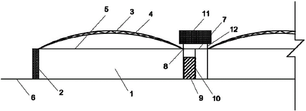
[0033] For areas with heavy precipitation and high groundwater table, it is preferable to build the solar greenhouse above the level ground 6 to prevent rainwater from pouring back and groundwater gushing out, such asfigure 1 As shown, the outer protective wall 2 is located above the horizontal ground 6, and the outer protective wall 2 is a thermal insulation wall, preferably a sandwich composite brick wall; it is located in the distributed photovoltaic multi-span trough solar greenhouse A windshield wall 15 is arranged above the outer protective wall body 2 on the north side, and its height is not lower than the height of the greenhouse ridge, and the south side wall body can also be constructed with double-layer hollow glass or sun panels.

[0034] Wherein, the heat storage and temperature adjustment unit includes a hot water storage body 9, a box or bag containing the hot water storage body 9, and an electric heater and a temperature control sensor installed in the box or bag...

Embodiment 2

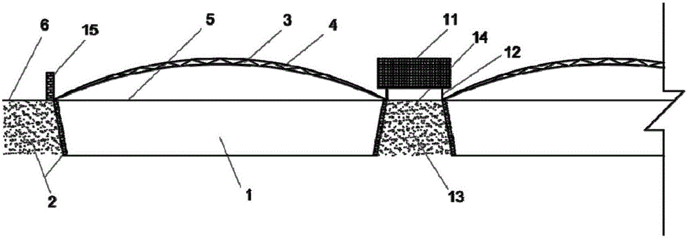
[0042] The difference between embodiment 2 and embodiment 1 is that embodiment 2 is mainly aimed at areas where the groundwater level is lower than 3m and the annual rainfall is below 200mm, such as the arid region of the northwest plateau in China, and the greenhouse floor is preferably dug 1.8-2m. Excavate multiple greenhouse slots side by side in the east-west direction on flat land, such as figure 2 As shown, the outer protective wall 2 is located below the horizontal ground 6, the upper surface of the outer protective wall 2 is flat with the horizontal ground 6, and the outer protective wall 2 is formed after digging underground. Earth wall, and choose brick wall to build protection, prevent landslide; Be positioned at the top of described outer protective wall body 2 around described distributed photovoltaic multi-span trough type solar greenhouse to be provided with windshield wall 15, preferably brick wall structure, wherein The height of the windshield wall 15 on the...


PUM


Abstract

The invention relates to the field of greenhouse engineering and photovoltaic technology and discloses a distributive photovoltaic multi-span trough-type sunlight greenhouse. The distributive photovoltaic multi-span trough-type sunlight greenhouse comprises multiple greenhouse units sequentially arranged along the east-west direction. A gap is kept between adjacent greenhouse units. Each gap is provided with a thermal storage temperature-regulation unit used for providing heat to the two adjacent greenhouse units. A solar cell panel is arranged above each thermal storage temperature-regulation unit. The invention further discloses an energy control method for the distributive photovoltaic multi-span trough-type sunlight greenhouse. The energy control method is capable of reducing mutual interference and unfavorable competition of greenhouse production and photovoltaic power generation so that luminous energy and space can be distributed in a balanced manner. Therefore, per-unit land area agriculture and photovoltaic benefit can be maximized.

Description

technical field [0001] The invention relates to the fields of greenhouse engineering and photovoltaic technology, in particular to a distributed photovoltaic multi-span trough solar greenhouse and an energy control method. Background technique [0002] Photovoltaic power generation is a technology that directly converts light energy into electrical energy by using the photovoltaic effect of the semiconductor interface. Distributed photovoltaic power generation refers to that it is located near the user, and the operation mode is mainly for the user's own use. A power generation facility characterized by system balance regulation in a distribution network. Photovoltaic power generation has gradually become one of the most concerned emerging industries in the world today because of its clean, pollution-free, renewable, energy-saving and emission-reducing properties, and its huge development potential. After the EU and other countries' "dump and countermeasures", my country's ...

Claims


Application Information

Patent Timeline
IPC IPC(8): A01G9/14A01G9/26
CPCA01G9/14A01G9/26Y02A40/25Y02P60/12
Inventor 郭文忠孙维拓陈红陈晓丽王利春贾冬冬聂铭君赵倩
Owner 农芯(南京)智慧农业研究院有限公司
Learn More