Novel horizontal tube type sedimentation pond

A technology of horizontal pipes and sedimentation tanks, which is applied in the direction of sedimentation separation, settling tanks, feeding/discharging devices of settling tanks, etc. It can solve the problems of discounted clarification capacity, inconvenient processing, difficult manufacturing and high production costs, and achieves guaranteed The effect of mud discharge, simple and reasonable design, and convenient processing and manufacturing

Inactive Publication Date: 2016-09-21
张良纯
View PDF8 Cites 4 Cited by
  • Summary
  • Abstract
  • Description
  • Claims
  • Application Information

AI Technical Summary

Problems solved by technology

[0002] At present, there are many types of sedimentation tanks on the market, such as advection sedimentation tanks, inclined plate sedimentation tanks, inclined tube sedimentation tanks, and labyrinth sedimentation tanks. , Horizontal sedimentation tank) have the following disadvantages: poor sedimentation effect, easy to cause reversible operation of suspended solids, low utilization rate of sedimentation tank, small water flow area, the above points restrict the sedimentation effect of the sedimentation device to a certain extent, so that Its clarification ability is greatly reduced
Compared with the previous sedimentation tank, this horizontal tube sedimentation and separation device has been greatly improved, but it still has the following disadvantages: (1) The parallel inclined plates of each unit are composed of upper and lower inclined plates, and the partitions are arranged on two parallel inclined plates. Between the boards, it is extremely inconvenient to process, and the manufacturing difficulty and manufacturing cost are very high
(2) The upper and lower inclined plates are arranged in parallel, and a sludge slideway is formed between adjacent inclined plates. The sludge slideway is a slender channel with the same upper and lower width. This design is only suitable for relatively good water quality. In the occasions where the sludge concentration is high, the sedimentation effect will be very poor. This is because the upper layer of sludge slides down the sludge slide from top to bottom, and the bottom layer has the highest concentration of sludge, and the sludge accumulates At most, it has a great impact on the mud discharge effect of the bottom water flow channel
(3) The bottom of the sludge chute forms a sludge discharge window through reinforcing ribs. Since the upper layer of sludge continues to slide down from top to bottom, the bottom layer of sludge is very easy to accumulate. This situation not only affects the sewage in the bottom water flow channel The sedimentation effect of the mud has a greater impact, and to a certain extent affects the operation of the sludge slide

Method used


Image

  • Novel horizontal tube type sedimentation pond
  • Novel horizontal tube type sedimentation pond
  • Novel horizontal tube type sedimentation pond

Examples


Embodiment 1

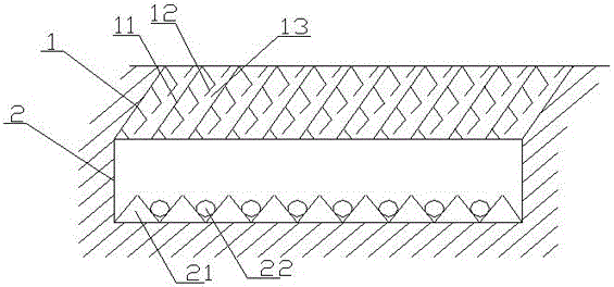
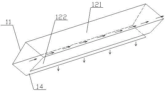
[0036] Such as figure 1 , figure 2 As shown, the upper sedimentation separation device 1 includes several parallel horizontal pipe units and sludge slides 13 formed between two adjacent horizontal pipe units. At least one of the two ends of the sludge slides 13 is closed, so that the sludge slides 13 is a still water area, which is conducive to sludge settlement. The horizontal pipe unit includes a sloping plate 11 and several partitions 12 arranged at intervals on the lower side of the sloping plate 11. When the sloping plate 11 is processed and connected with the partition 12, it is more convenient, and it is only necessary to fix the sloping plate 11 and the partition 12 in sequence. The partition plate 12 is a V-shaped plate whose cross-section is formed by the plate surface A121 and the plate surface B122, and the opening faces the inclined plate. The plate surface A121 is arranged on the side of the inclined plate 11, between the plate surface A121 and the plate surfac...

Embodiment 2

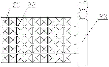
[0040] Such as Figure 8 As shown, on the basis of Example 1, the bottom of the sedimentation tank is funnel-shaped, and the angle between the side wall of the bottom of the tank and the horizontal plane is 45-75 degrees, and the sludge discharged from the upper sedimentation separation device 1 is directly collected into the sedimentation tank The bottom of the pool is connected to the sludge discharge supervisor 23, and the sludge discharge supervisor 23 has a sludge discharge valve 24. When the sludge accumulates to a certain extent at the bottom of the pool, the sludge discharge valve 24 is opened, and the sludge is discharged from the sedimentation tank.

Embodiment 3

[0042] Such as Figure 9 As shown, on the basis of Embodiment 1 or 2, several groups of horizontal pipe units and sludge slideways form a main body with a quadrangular cross-section, and the outside of the main body is covered with a formwork 6 with a quadrilateral cross-section that fits with it. The frame 6 can be a prismatic frame with a quadrangular cross-section, or can be made of grid material to facilitate mud discharge, and make the bottom of the sludge slideway 13 a continuous mud discharge groove; Set in parallel to form a sedimentation and separation device, and produce scattered sedimentation and separation devices in a modular form, which is convenient for transportation and installation.


PUM


Abstract

The invention relates to a novel horizontal tube type sedimentation pond. The novel horizontal tube type sedimentation pond comprises an upper precipitation separation device and a lower precipitation sludge discharging device, wherein the precipitation separation device comprises horizontal tube units and sludge chutes; each horizontal tube unit comprises an inclined plate, and a plurality of separating plates which are arranged at intervals on the lower side surface of each inclined plate; each separating plate is a V-shaped plate consisting of a surface A and a surface B, and an opening of the section of each V-shaped plate is toward the corresponding inclined plate; each surface A is arranged on the side surface of the corresponding inclined plate; all surfaces A are parallel to each other; the planes of the surfaces B are parallel to or intersected with the plane of the corresponding inclined plates; all surfaces B are parallel to each other; a sludge discharging opening is left between every two adjacent separating plates on the same inclined plate. The novel horizontal tube type sedimentation pond has the advantages that the horizontal tube units comprise the inclined plates and the separating plates, so that the convenience of processing, manufacturing and mounting is ensured; channels being narrow in upper part and wide in lower part can be formed by the sludge chutes between adjacent horizontal tube units, so that the distribution condition that more sludge is at the lower part of each sludge chute and less sludge is at the upper part of each sludge chute apply is adapted, and as a result, the high efficiency of the precipitation separation device can be ensured.

Description

technical field [0001] The invention relates to the technical field of water purification, in particular to a novel horizontal tube sedimentation tank. Background technique [0002] At present, there are many types of sedimentation tanks on the market, such as advection sedimentation tanks, inclined plate sedimentation tanks, inclined tube sedimentation tanks, and labyrinth sedimentation tanks. , Horizontal sedimentation tank) have the following disadvantages: poor sedimentation effect, easy to cause reversible operation of suspended solids, low utilization rate of sedimentation tank, small water flow area, the above points restrict the sedimentation effect of the sedimentation device to a certain extent, so that Its clarification ability is greatly reduced. [0003] Patent No. 200610123752.2 mentions a horizontal tube sedimentation and separation device, which includes multiple sets of parallel sloping plates. Each set of parallel sloping plates is composed of an upper slo...

Claims


Application Information

Patent Timeline
Patent Type & Authority Applications(China)
IPC IPC(8): B01D21/02B01D21/24
CPCB01D21/02B01D21/0045B01D21/0051B01D21/245
Inventor 贾贝尔
Owner 张良纯
Why Eureka
Try Eureka