Dust removing and filtering device based on honeycomb ceramic filter elements

A technology of honeycomb ceramics and filter devices, which is applied in the direction of filtration separation, membrane filter, and dispersed particle filtration, etc., which can solve the problems of increasing energy consumption and increasing equipment investment, and achieves large gas throughput, high blowback frequency, and structural strength and the effect of high material strength

Inactive Publication Date: 2016-09-21
德州奥深节能环保技术有限公司
View PDF11 Cites 8 Cited by
  • Summary
  • Abstract
  • Description
  • Claims
  • Application Information

AI Technical Summary

Problems solved by technology

[0002] At present, the maximum operating temperature of the high-temperature exhaust gas dust removal and filtering device does not exceed 260°C. In recent years, in order to purify the harmful components in the exhaust gas, use waste heat and recover valuable components from the high-temperature gas, it is urgently required that the temperature of the clean gas at the outlet of the dust removal equipment reach Temperatures above 250°C or even higher, such as the active reaction temperature of industrial waste gas denitrification catalysts are generally 250°C-450°C, using dust removal equipment with ordinary filter materials, the temperature of the clean exhaust gas at the outlet cannot meet the reaction requirements, and additional auxiliary heating must be added The device can meet the process requirements, which not only increases equipment investment, but also increases energy consumption
At the same time, the requirements for installation in a small space, as well as the requirements for the use of flame-retardant, anti-static or high-humidity dusty exhaust gas filtration, are also unsatisfactory for dust removal equipment using common filter materials. Above high temperature environment, and with flame retardant, anti-static and non-absorbent dust filter device

Method used


Image

  • Dust removing and filtering device based on honeycomb ceramic filter elements
  • Dust removing and filtering device based on honeycomb ceramic filter elements
  • Dust removing and filtering device based on honeycomb ceramic filter elements

Examples


Embodiment Construction

[0039] The implementation of the present invention will be illustrated by specific specific examples below, and those skilled in the art can easily understand other advantages and effects of the present invention from the contents disclosed in this specification.

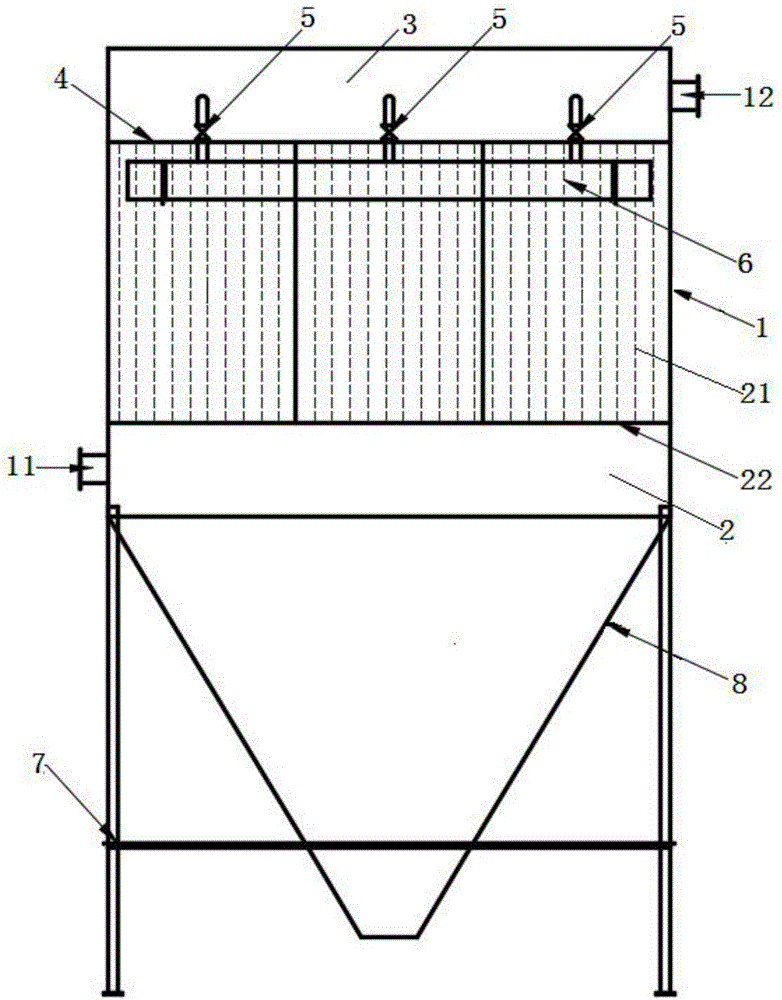
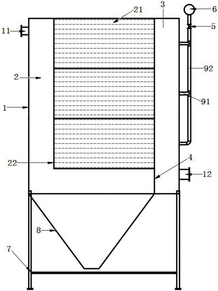
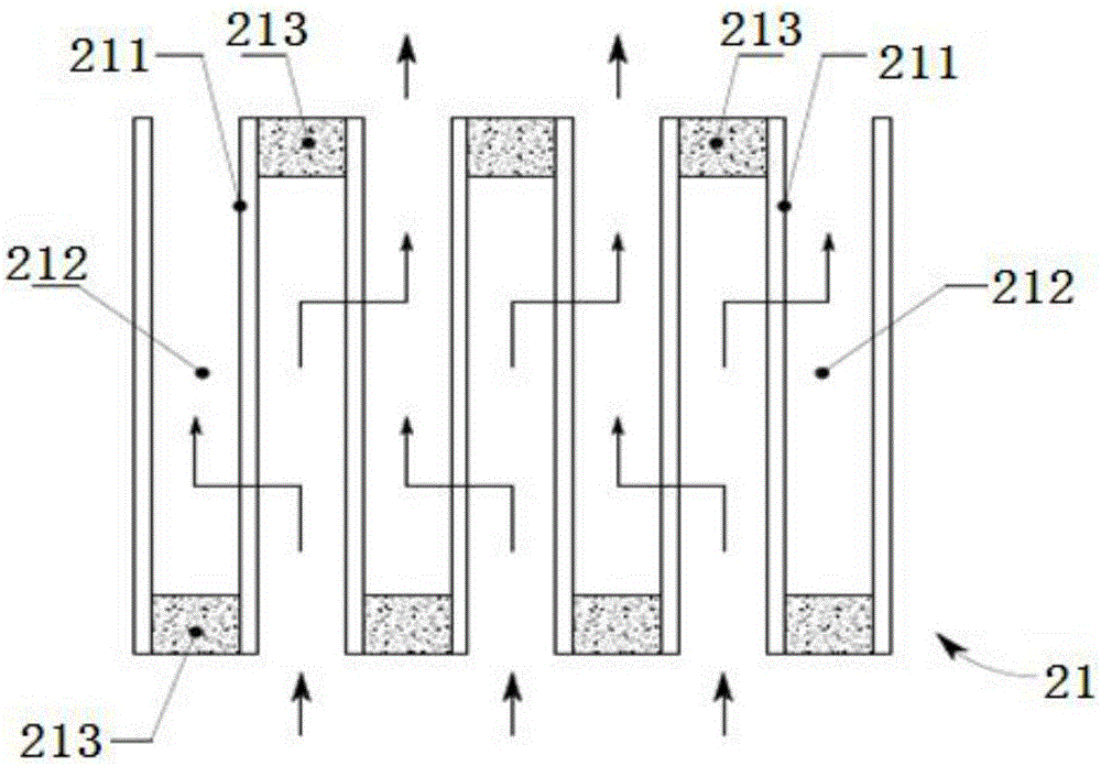
[0040] see Figure 1 to Figure 3 It should be noted that the structures, proportions, sizes, etc. shown in the drawings attached to this specification are only used to match the content disclosed in the specification, for those who are familiar with this technology to understand and read, and are not used to limit the implementation of the present invention. Limiting conditions, so there is no technical substantive meaning, any modification of structure, change of proportional relationship or adjustment of size, without affecting the effect and purpose of the present invention, should still fall within the scope of the present invention. within the scope covered by the disclosed technical content. At the same time,...


PUM

PropertyMeasurementUnit
thicknessaaaaaaaaaa

Abstract

The invention provides a dust removing and filtering device based on honeycomb ceramic filter elements. The dust removing and filtering device comprises a shell, a dust cavity, a clean cavity, a dust removal fan and a compressed air cylinder, wherein a waste gas inlet is formed in one side of the shell, and a purified gas outlet is formed in the other side of the shell; the dust cavity is formed inside the shell and is communicated with one end of the waste gas inlet, and at least one ceramic filter body is arranged inside the dust cavity; the clean cavity is formed inside the shell, a cavity partition plate is mounted between the clean cavity and the dust cavity and is connected with one end of the purified gas outlet; the dust removal fan is connected with the other end of the purified gas outlet; the compressed air cylinder is connected with the clean cavity through a pipeline, and a pulse inverse blow control valve is arranged on the pipeline. A dust removing and filtering device body adopts the ceramic filter body to filter dust, and the structural strength and the material strength of the dust removing and filtering device body are strong, so that the filter body cannot generate breakage, deformation, corrosion and other damages; as the pulse inverse blow control valve is adopted for controlling compressed air to flow out from the air cylinder so as to blow the dust on the ceramic filter body, the dust removing and filtering device provided by the invention has excellent dust down performance.

Description

technical field [0001] The invention relates to the field of dust removal devices, in particular to a dust removal filter device based on a honeycomb ceramic filter element. Background technique [0002] At present, the maximum operating temperature of the high-temperature exhaust gas dust removal and filtering device does not exceed 260°C. In recent years, in order to purify the harmful components in the exhaust gas, use waste heat and recover valuable components from the high-temperature gas, it is urgently required that the temperature of the clean gas at the outlet of the dust removal equipment reach Temperatures above 250°C or even higher, such as the active reaction temperature of industrial waste gas denitrification catalysts are generally 250°C-450°C, using dust removal equipment with ordinary filter materials, the temperature of the clean exhaust gas at the outlet cannot meet the reaction requirements, and additional auxiliary heating must be added The device can me...

Claims


Application Information

Patent Timeline
Patent Type & Authority Applications(China)
IPC IPC(8): B01D46/24B01D39/20
CPCB01D39/20B01D46/2422B01D2273/28B01D2267/30B01D46/58Y02A50/2351
Inventor 武雄晖潘吉庆倪寿才
Owner 德州奥深节能环保技术有限公司
Why Eureka
Try Eureka