
Roll painting device and tower drum operational equipment

A technology of roller coating and roller coating mechanism, which is applied to the device and coating of surface coating liquid, which can solve the problems of manual coating work intensity, low degree of automation, bulky and cumbersome equipment, etc., and achieve compact and convenient structure , Improve work efficiency and reduce the overall volume

Inactive Publication Date: 2016-09-21
SANY ELECTRIC CO LTD
View PDF6 Cites 2 Cited by
  • Summary
  • Abstract
  • Description
  • Claims
  • Application Information

AI Technical Summary

Problems solved by technology

[0004] The purpose of the present invention is to provide a roller coating device and tower operation equipment to solve the problems in the prior art of manual coating with high work intensity, bulky and heavy equipment, serious environmental pollution, low degree of automation and high painting cost. question

Method used


Image

  • Roll painting device and tower drum operational equipment
  • Roll painting device and tower drum operational equipment

Examples


Embodiment 1

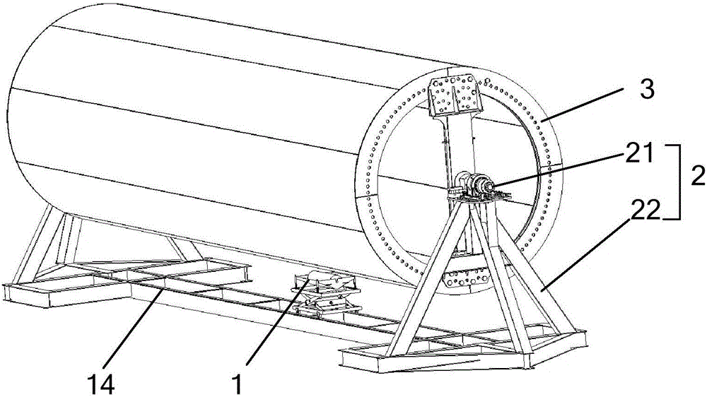
[0031] to combine figure 1 , figure 2 As shown, the roller coating device provided by the present embodiment one includes a power mechanism 2 and a roller coating mechanism 1; One is the active part, and the other is the driven part; the power mechanism 2 includes a drive unit 21, the drive unit 21 is used to drive the active part to rotate around its own axis, and the driven part drives the driven part to rotate, thereby realizing automatic rolling. Paint function. The roller coating device is suitable for large-sized objects to be coated, such as tower tubes. The device can not only reduce the working intensity, but also improve the working efficiency and reduce the cost of painting.

[0032] It is worth noting that, for the selection of the driving part and the driven part, it can be flexibly selected depending on the specific size of the object 3 to be coated. When the object to be coated 3 is a large-sized cylindrical object, it is preferable to use the object to be c...

Embodiment 2

[0056] The tower operation equipment provided in the second embodiment includes the roller coating device in the first embodiment. The tower operation equipment provided in the second embodiment can be applied in the roll coating process of wind power towers. The automatic coating of the wind power tower is realized by the roller coating device.

[0057] The coating process of the wind power tower will be described in detail below in combination with the specific structure of the roller coating device.

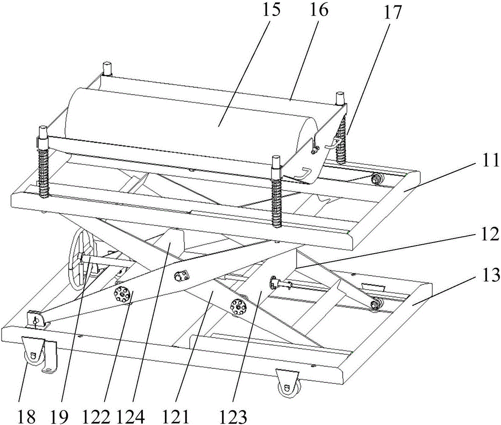
[0058] combine figure 1 , figure 2 As shown, the roller coating device includes a power mechanism 2 and a roller coating mechanism 1 . Wherein, the roller coating mechanism 1 includes a roller brush 15 for painting the outer peripheral surface of the wind power tower. One of the rolling brush 15 and the wind power tower is a driving part, and the other is a driven part. That is to say, the rolling brush 15 can be flexibly selected as a driven part or a driving part depen...


PUM


Abstract

The invention discloses a roll painting device and tower drum operational equipment. The roll painting device comprises a power mechanism and a roll painting mechanism, wherein the roll painting mechanism comprises a rolling brush for painting a to-be-painted object; one of the rolling brush and the to-be-painted object is a driving part, and the other of the rolling brush and the to-be-painted object is a driven part; the power mechanism comprises a driving unit; the driving unit is used for driving the driving part to rotate around the self axis, and the driving part drives the driven part to rotate to realize the automatic roll painting function. The roll painting device is applicable to large-size painted objects, such as a tower drum, and can alleviate the operating strength, improve the working efficiency and reduce the painting cost.

Description

technical field [0001] The invention relates to the technical field of roller coating, in particular to a roller coating device and tower operation equipment. Background technique [0002] As the single unit capacity of the wind turbine increases, the diameter and height of the tower are also gradually increasing, and at the same time, the workload and difficulty of the surface coating of the tower are increased. [0003] At present, the painting of the tower tube is usually carried out by manual roller brushing, but due to the large surface area of ​​the painting, the labor intensity is high, and the manual painting efficiency is low. Moreover, due to the large volume of the tower itself, the volume of the corresponding painting equipment is also very large, which not only makes the painting equipment bulky and inconvenient to operate, but also causes environmental deterioration due to large-area paint leakage. It will also have a certain impact on the body of the operator...

Claims


Application Information

Patent Timeline
IPC IPC(8): B05C1/08
CPCB05C1/08
Inventor 林利明贾海云蔡政
Owner SANY ELECTRIC CO LTD
Features
  • Generate Ideas
  • Intellectual Property
  • Life Sciences
  • Materials
  • Tech Scout
  • Unparalleled Data Quality
  • Higher Quality Content
  • 60% Fewer Hallucinations
Learn More