Sludge drying full-automatic production line

A sludge drying, fully automatic technology, applied in sludge treatment, fixed/solidified sludge treatment, water/sludge/sewage treatment, etc. The mud is not strong enough to achieve the effect of lightening the load, not easy to loosen, and setting reasonable

Active Publication Date: 2016-09-21
GUANGZHOU KAINENG ELECTRIC EQUIP
View PDF6 Cites 14 Cited by
  • Summary
  • Abstract
  • Description
  • Claims
  • Application Information

AI Technical Summary

Problems solved by technology

The stirring mechanisms in these sludge forming machines are similar, and they are all used to stir the sludge to make it loose. However, after the sludge is broken up, its viscosity is still very high, and it is difficult to smoothly enter the forming process only relying on the gravity of the sludge itself. The mold is formed in the drum; the gap between the loose sludge is large, and the sludge is often intermittent after passing through the forming drum. The sludge formed is not strong enough, and it is easy to disperse during transportation and drying, which seriously affects the subsequent sludge drying. Chemicalized product quality
In addition, due to the large contact area between the stirring mechanism and the sludge, and the weight of the sludge itself is heavy, this will increase the load on the stirring mechanism, and the motor driving the stirring head will be easily burned

Method used


Image

  • Sludge drying full-automatic production line
  • Sludge drying full-automatic production line
  • Sludge drying full-automatic production line

Examples


Embodiment Construction

[0029] The present invention will be further described below in conjunction with the accompanying drawings of the description.

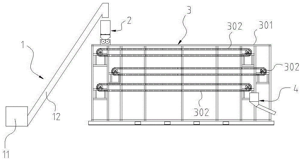
[0030] Such as figure 1 As shown, a fully automatic sludge drying production line includes a feeder 1, a sludge forming machine 2, a drying dehumidifier 3, and a discharger 4 in sequence according to the conveying direction of the material.

[0031] Such as figure 1 As shown, the feeder 1 includes a feed barrel 11 and a screw lifting mechanism 12, and the feed barrel 11 is docked with the sludge forming machine 2 through the screw lifting mechanism 12. The sludge forming machine 2 is set on the top of the drying dehumidifier 3, and the feeding barrel 11 is set at a lower position for the convenience of feeding, so the screw lifting mechanism 12 is needed to transport the material to the sludge forming machine 2. When the screw elevator is conveying the material, the material is chopped and decomposed by the agitation of the spiral blade.

[0032] ...


PUM


Abstract

The invention relates to a sludge drying full-automatic production line. Along the material conveying direction, the sludge drying full-automatic production line sequentially comprises a feeder, a sludge forming machine, a drying dehumidifier and a discharger, wherein the sludge forming machine comprises a sludge tank, a forming roller and a stirring pressurization cutter; the top of the sludge tank is provided with a feed port, the bottom of the sludge tank is provided with a discharge port, and the forming roller is arranged at the discharge port of the sludge tank; the stirring pressurization cutter comprises a rotating shaft, a driving mechanism for driving the rotating shaft to rotate, and more than two blades which are circumferentially uniformly distributed on the periphery of the rotating shaft; the blades are connected with the rotating shaft through connecting rods; one surface of each blade facing towards the rotating shaft is a joint surface, and the other surface away from the rotating shaft is a pressurization surface which is cambered; and when the blades rotate to the bottommost end, the cambered pressurization surface of each blade can apply a certain pressure to the sludge at the forming roller, so that the accumulated sludge becomes compact, and the compacted sludge is extruded into the forming roller to be formed, so that the formed sludge has favorable continuity and is compact without easily becoming loose.

Description

technical field [0001] The invention relates to sludge drying equipment, in particular to an automatic sludge drying production line. Background technique [0002] With the development of urban construction and the improvement of living standards, the generation of urban domestic sludge is also increasing, and the long-term accumulation will greatly affect the urban environment and air quality. At present, the methods of batch treatment of municipal domestic sludge are generally physical methods and biochemical methods. The physical method is generally drying treatment, that is, removing most of the water contained in the sludge, and then performing harmless treatment on the remaining slag. be processed or diverted to other uses. Compared with biochemical treatment, physical drying treatment has significant advantages, such as small footprint of treatment equipment, short treatment cycle, low energy consumption, and less likely to cause secondary pollution. However, in the...

Claims


Application Information

Patent Timeline
Patent Type & Authority Applications(China)
IPC IPC(8): C02F11/00C02F11/12
CPCC02F11/00C02F11/008C02F11/12
Inventor 吴金城
Owner GUANGZHOU KAINENG ELECTRIC EQUIP
Why Eureka
Try Eureka