Electrolytic production device for rare earth alloy

A technology for production equipment and rare earth alloys, applied in the direction of electrolysis process, electrolysis components, electrodes, etc., can solve the problems of waste, high energy consumption of electrolysis reaction, increase of production cost, etc., and achieve reduction of abnormal production loss, uniform upper and lower temperatures, Effect of Reducing Reactive Current Consumption

Inactive Publication Date: 2016-09-21
NINGBO FUNENG NEW MATERIAL
View PDF6 Cites 3 Cited by
  • Summary
  • Abstract
  • Description
  • Claims
  • Application Information

AI Technical Summary

Problems solved by technology

The disadvantages of the existing rare earth alloy electrolysis production equipment are: 1. The electrolyte in the graphite electrolytic cell is static. During the electrolysis process, the back side of the graphite anode is prone to carbide slagging, so that the graphite anode can directly The voltage and current transmission to the graphite electrolytic cell, this part of the electric energy is a waste of no effect on the electrolytic reaction, so the energy consumption of the electrolytic reaction is large; 2. When the graphite anode directly transmits the voltage and current to the graphite electrolytic cell during the electrolysis process, The abnormal conversion of the cathode and anode of the graphite electrolytic cell leads to the abnormal production loss of the graphite electrolytic cell in the electrolytic production and increases the production cost; 3. Since the graphite anode will be continuously consumed during the electrolysis reaction, the distance between the graphite anode and the cathode 4. During the production process, the electrolyte is not fluid, so the temperature of the electrolyte in the graphite electrolytic cell cannot be uniform, and slagging is easy to occur

Method used


Image

  • Electrolytic production device for rare earth alloy
  • Electrolytic production device for rare earth alloy

Examples


Embodiment Construction

[0014] The present invention will be described in further detail below in conjunction with the accompanying drawings and specific embodiments.

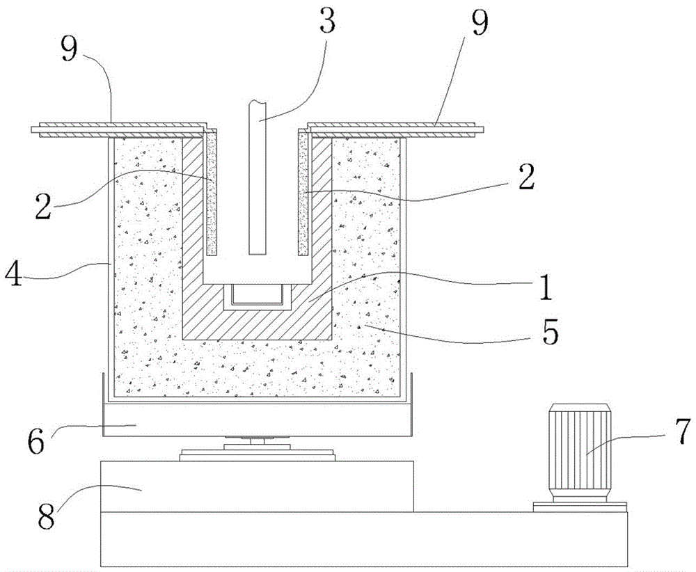
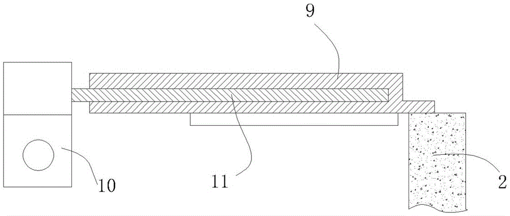
[0015] refer to figure 1 , figure 2 , a rare earth alloy electrolytic production equipment, comprising a graphite electrolytic cell 1, a graphite anode 2 extending into the graphite electrolytic cell 1, and a cathode 3 extending into the graphite electrolytic cell 1.

[0016] It also includes a sheath 4, and a thermal insulation layer 5 is provided between the sheath 4 and the graphite electrolytic cell 1.

[0017] It also includes a rotary drive mechanism, which is in transmission connection with the graphite electrolytic cell 1 so that the rotary drive mechanism can drive the graphite electrolytic cell 1 to rotate.

[0018] In this embodiment, the graphite electrolytic cell 1 is placed in a base 6 , and the rotation driving mechanism is connected with the base 6 . The rotary drive mechanism includes a rotary drive motor 7 and a ...


PUM


Abstract

The invention discloses an electrolytic production device for a rare earth alloy. The electrolytic production device comprises a graphite electrolytic bath, graphite anodes stretching into the graphite electrolytic bath, and a cathode stretching into the graphite electrolytic bath, and further comprises a protective jacket and a rotating driving mechanism, wherein a thermal insulation layer is arranged between the protective jacket and the graphite electrolytic bath; and the rotating driving mechanism is in transmission connection with the graphite electrolytic bath, so that the rotating driving mechanism can drive the graphite electrolytic bath to rotate. According to the electrolytic production device, during the electrolytic process, the rotating driving mechanism drives the graphite electrolytic bath to rotate, an electrolyte in the graphite electrolytic bath is dynamic, carbide slag is not liable to generate on the back surfaces of the graphite anodes, the direct voltage and current transmission of the graphite anodes to the graphite electrolytic bath is obstructed, the reactive current consumption is reduced, and the purpose of energy consumption is achieved; and the direct voltage and current transmission of the graphite anodes to the graphite electrolytic bath is obstructed, so that the service life of the graphite electrolytic bath is further prolonged.

Description

technical field [0001] The invention relates to a rare earth alloy electrolytic production equipment. Background technique [0002] The rare earth electrolysis process is a process in which rare earth metal fluoride (REF) molten salt is used as electrolyte, rare earth metal oxide (REO) is dissolved in the electrolyte, and electrolytic reaction is carried out at high temperature to produce rare earth alloy. Rare earth alloy electrolysis production equipment generally includes a graphite electrolytic cell, a graphite anode extending into the graphite electrolytic cell, and a cathode extending into the graphite electrolytic cell. The electrolyte is located in the graphite electrolytic cell during the electrolytic reaction; it also includes a sheath. A thermal insulation layer is provided between the sleeve and the graphite electrolytic cell. The disadvantages of the existing rare earth alloy electrolysis production equipment are: 1. The electrolyte in the graphite electrolytic...

Claims


Application Information

Patent Timeline
Patent Type & Authority Applications(China)
IPC IPC(8): C25C7/02C25C3/36
CPCC25C7/025C25C3/36
Inventor 郑巨根邹宁
Owner NINGBO FUNENG NEW MATERIAL
Why Eureka
Try Eureka