Supercharge Your Innovation With Domain-Expert AI Agents!

A New Type of Spindle Rammer

A spindle-shaped, rammer technology, applied in the field of new spindle-shaped rammers, can solve the problems of tamper cracks, aggravating the surface of the rammer to form ravines, scratches, cracks, etc., to improve wear resistance and corrosion resistance, extrusion The effect of soil compaction is good and the use cycle is improved

Active Publication Date: 2019-01-08
SICHUAN JIUDINGZHIYUAN INTPROP OPERATIONS CO LTD
View PDF8 Cites 0 Cited by
  • Summary
  • Abstract
  • Description
  • Claims
  • Application Information

AI Technical Summary

Problems solved by technology

However, in the rammers of the existing dynamic tamping machines, most of them are cylindrical flat-bottomed rammers, and there are few reports about special-shaped rammers. In the process of squeezing the soil, there is often a certain degree of "suction hammer" phenomenon. At the same time, when the rammer hits with a hard object, the hard object directly acts on the rammer, which may cause the rammer The surface of the hammer forms an uneven section, which in turn destroys the strength of the rammer, causing cracks or even cracks to appear on the surface of the rammer. When the hammer is lifted and lowered, the friction between the side of the rammer and the soil will aggravate the surface of the rammer and form a ravine. , Scratches, cracks and scratches cause corrosive substances in the soil to hide in it and strongly corrode the interface. The consequence is that the surface of the rammer is more severely corroded, which in turn causes the rammer to fail prematurely. This is undoubtedly Increased equipment input costs

Method used


Image

  • A New Type of Spindle Rammer
  • A New Type of Spindle Rammer
  • A New Type of Spindle Rammer

Examples


Embodiment 2

[0035] Embodiment two is the same as embodiment one, and its difference is that, casting infiltration process comprises the following steps:

[0036] Step 1. Weigh TiC alloy powders with an average particle size of 200 μm and put them into a ball mill, mix them evenly with water glass, flux borax and alcohol to form a paste mixture for later use, wherein the mass content of each component in the TiC alloy powder is: TiC 57% for Mn, 6% for Ni, 2% for Ni, 0.5% for Nb, 5% for Cr, 7% for WC, and the balance is iron. The amount is 5.7% of the weight of TiC alloy powder;

[0037] Step 2, apply the prepared paste mixture evenly in the mold cavity, the coating thickness is 4mm, after the coating is completed, ignite the paste mixture, so that the paste mixture solidifies and adheres in the mold cavity, spare;

[0038] Step 3. Put the mold coated with the mixture into a heat treatment furnace and bake at 250°C for 3 hours, then take it out and air cool;

[0039] Step 4: Melt molten ...

Embodiment 3

[0043] Embodiment three is the same as embodiment one and embodiment two, and its difference is that, casting infiltration process comprises the following steps:

[0044] Step 1. Weigh TiC alloy powders with an average particle size of 235 μm and put them into a ball mill, and mix them evenly with water glass, flux borax and alcohol to form a paste mixture for later use. The mass content of each component in the TiC alloy powder is: TiC is 55%, Mn is 4.5%, Ni is 1.4%, Nb is 0.47%, Cr is 3.6%, WC is 5.8%, and the balance is iron. The amount is 5.7% of the weight of TiC alloy powder;

[0045] Step 2, apply the prepared paste mixture evenly in the mold cavity, the coating thickness is 4mm, after the coating is completed, ignite the paste mixture, so that the paste mixture solidifies and adheres in the mold cavity, spare;

[0046] Step 3. Put the mold coated with the mixture into a heat treatment furnace and bake at 250°C for 3 hours, then take it out and air cool;

[0047] Ste...

Embodiment 4

[0051] Embodiment four is the same as embodiment one, embodiment two and embodiment three, and its difference is that casting infiltration process comprises the following steps:

[0052] Step 1. Weigh TiC alloy powders with an average particle size of 250 μm and put them into a ball mill, mix them evenly with water glass, flux borax and alcohol to form a paste mixture for later use, wherein the mass content of each component in the TiC alloy powder is: TiC is 53%, Mn is 4%, Ni is 1%, Nb is 0.4%, Cr is 3%, WC is 5%, and the balance is iron. The amount of water glass added is 5% of the weight of TiC alloy powder, and the flux is added The amount is 5.7% of the weight of TiC alloy powder;

[0053] Step 2, apply the prepared paste mixture evenly in the mold cavity, the coating thickness is 4mm, after the coating is completed, ignite the paste mixture, so that the paste mixture solidifies and adheres in the mold cavity, spare;

[0054] Step 3. Put the mold coated with the mixture...


PUM


Abstract

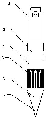
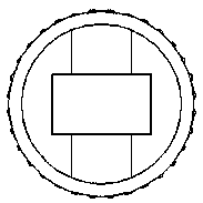
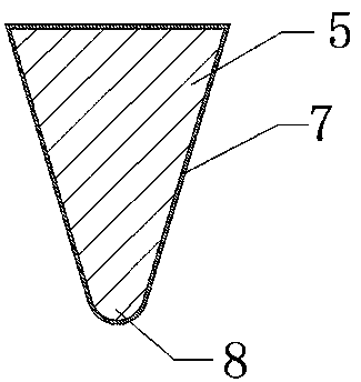
The invention discloses a novel fusiform rammer. The novel fusiform rammer comprises a rammer body. One end of the rammer body is fixedly connected with a transition part. The other end of the rammer body is fixedly connected with an extrusion part. The side face of the rammer body is provided with an outwards-protruded gear-shaped protrusion. After combined, the transition part, the rammer body and the extrusion part are fusiform. One end of the transition part is connected with the rammer body seamlessly. An installation part connected with a rammer joint fixedly in a matched mode is arranged at the other end of the transition part. One end of the extrusion part is connected with the rammer body seamlessly. A rammer head is fixedly connected with the other end of the extrusion part. The structure and composition of the rammer are optimized, so that when the rammer is lifted and put down, friction force of the side face of the rammer and a soil body is reduced, and thus scratches are not liable to be formed on the side face of the rammer. Through the fusiform shape of the rammer, extrusion force of the rammer and a hard object can be reduced, so that a concave-convex interface is not liable to be formed on the surface of the rammer, and thus the soil extrusion compact effect is good. In addition, through an additionally arranged cast infiltrated layer, the abrasion resistance and corrosion resistance of the rammer can be improved substantially, and thus the service cycle of the rammer is prolonged.

Description

technical field [0001] The invention relates to the field of dynamic tamping machine equipment, in particular to a novel spindle-shaped rammer. Background technique [0002] In the current hole-forming technology, most of the holes are formed by borrowing soil or drilling soil, which has a great destructive effect on the original soil and is not conducive to further exerting the bearing capacity of the soil. The existing immersed tube squeezes the soil to form holes. However, the scope of application is small and more limited. [0003] The use of special-shaped rammers to squeeze soil into holes is a new construction method developed by technicians today. By using special-shaped rammers, the soil can be forced to squeeze the soil during the hole-forming process, so that the soil around the holes can be obtained. It has a good compaction and reinforcement effect and improves the bearing capacity of the soil. However, in the rammers of the existing dynamic tamping machines, ...

Claims


Application Information

Patent Timeline
Patent Type & Authority Patents(China)
IPC IPC(8): E02D3/054
CPCE02D3/054
Inventor 汪崇营
Owner SICHUAN JIUDINGZHIYUAN INTPROP OPERATIONS CO LTD
Features
  • R&D
  • Intellectual Property
  • Life Sciences
  • Materials
  • Tech Scout
  • Unparalleled Data Quality
  • Higher Quality Content
  • 60% Fewer Hallucinations
Learn More