Cast in situ concrete tool type steel frame wood plastic template system and construction method thereof

A wood-plastic formwork and tool-type technology, which is applied in the fields of formwork/formwork components, on-site preparation of building components, and formwork processing, etc., can solve the problems of increasing formwork loss rate, low production efficiency, labor and labor, etc.

Inactive Publication Date: 2016-09-21
ANYANG INST OF TECH +1
View PDF6 Cites 2 Cited by
  • Summary
  • Abstract
  • Description
  • Claims
  • Application Information

AI Technical Summary

Problems solved by technology

The most widely used concrete formwork is the "fastener-type steel pipe supported plywood formwork system". The formwork system is composed of support poles, sweeping poles, horizontal tie Adjustable braces, main flute, secondary flute, and plywood constitute the formwork and its erection adjustment system. The formwork system needs to be dismantled as a whole. The process requires the cooperation of many people, the labor intensity is high, the production efficiency is low, and it is laborious
The spacing between formwork support poles is relatively random, and the construction standards are difficult to implement, resulting in frequent construction problems such as mold runout, grout leakage, and cracking, and even cause formwork collapse accidents. Existence, resulting in a large loss rate of the formwork, the formwork is nailed to the secondary corrugated board after splicing, the formwork of a room is basically a whole, it is impossible to disassemble in small pieces during the demoulding process, often the entire room is dismantled as a whole, it is impossible to do Handle with care, causing a lot of damage to the formwork during the demolition process, increasing the loss rate of the formwork, and seriously wasting formwork resources

Method used


Image

  • Cast in situ concrete tool type steel frame wood plastic template system and construction method thereof
  • Cast in situ concrete tool type steel frame wood plastic template system and construction method thereof
  • Cast in situ concrete tool type steel frame wood plastic template system and construction method thereof

Examples


Embodiment Construction

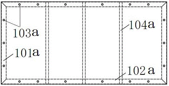
[0082] Each component of the present invention will be described in detail below in conjunction with the accompanying drawings. The tool-type steel-frame wood-plastic formwork system and its construction technology for cast-in-place concrete in the present invention refer to the tool-type steel-frame wood-plastic formwork system and its construction technology for cast-in-place concrete structures.

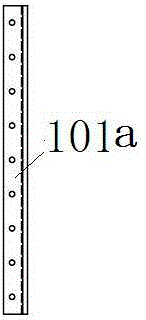
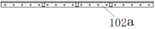
[0083] Tool type steel frame wood-plastic template as attached Figure 1 to Figure 10 As shown in the accompanying drawings, each mark in the tool-type steel frame wood-plastic formwork is: 101a: short outer frame; 102a: long outer frame; 103a: connection hole of the fixed-length formwork; 104a: back flute of the fixed-length formwork; 201a: short frame ;202a: long frame; 203a: U-shaped bracket; 204a: back corrugated of variable-scale formwork; 2021a: connecting surface of long frame and variable-scale wood-plastic panel; 2022a: connecting part of long frame and short frame; The ...


PUM


Abstract

A cast in situ concrete tool type steel frame wood plastic template system comprises a tool type steel frame wood plastic template, a tool type angle steel frame column template, a tool type variable column hoop, a tool type beam template support, a rapid support, and a support top connecting seat; said members are mutually connected to form the cast in situ concrete tool type steel frame wood plastic template system; the cast in situ concrete tool type steel frame wood plastic template system construction method comprises a steel bar concrete frame structure construction process and a steel bar concrete shear wall structure construction process; the steel frame wood plastic template system comprises the following processes: design, formwork, casting, and dismounting. The cast in situ concrete tool type steel frame wood plastic template system is standard, rapid in formwork, early in dismounting, high in efficiency, high in safety factor, economical and practical, low in carbon consumption, environment friendly, can save resources, and the recycle number can be above 500 times; even if the steel back frame cannot be restored, the cast in situ concrete tool type steel frame wood plastic template system can be fully recovered for producing steel; the system and method are low in comprehensive usage cost.

Description

technical field [0001] The invention relates to a building formwork system and construction technology, in particular to a tool-type steel-frame wood-plastic formwork system and construction technology for cast-in-place concrete, and belongs to the field of construction technology. Background technique [0002] In today's construction industry, concrete structures occupy a dominant position. The technological innovation and new technology promotion in the field of concrete formwork has broad market prospects. The characteristics of China's formwork industry are the large number of enterprises, small scale, low technical level, and the competition of modern enterprises. It is mainly reflected in the competition of innovation ability, which can continuously carry out continuous innovation on the basis of existing technology, so that the technological development of enterprises can lead the entire industry, and also obtain the competitiveness of enterprises. The most widely use...

Claims


Application Information

Patent Timeline
IPC IPC(8): E04G9/02E04G19/00
CPCE04G9/02E04G19/00E04G2009/023
Inventor 石志强高丽丽李文龙杨春生刘小旦寇俊洋
Owner ANYANG INST OF TECH
Why Eureka
Try Eureka