
Large displacement high pressure gear pump with driving and driven wheels in different sizes

A technology of different sizes and driven wheels, applied in the direction of rotary piston type/swing piston type pump parts, pumps, pump components, etc. The effect of force deformation, reduction of internal leakage, and low noise

Inactive Publication Date: 2016-09-21
江苏国瑞液压机械有限公司
View PDF6 Cites 6 Cited by
  • Summary
  • Abstract
  • Description
  • Claims
  • Application Information

AI Technical Summary

Problems solved by technology

Conventional external gear pumps have a simple structure and have the characteristics of large flow pulsation, high noise, low efficiency, low pressure, and severe stress on individual parts.
In order to improve the working performance of gear pumps, optimize the structure of parts and components, and prolong their service life, domestic and foreign experts, scholars and designers in enterprises have done a lot of research work, but gear pumps with different gear sizes used in walking machinery are still relatively small. few

Method used


Image

  • Large displacement high pressure gear pump with driving and driven wheels in different sizes
  • Large displacement high pressure gear pump with driving and driven wheels in different sizes
  • Large displacement high pressure gear pump with driving and driven wheels in different sizes

Examples


Embodiment Construction

[0017] The specific implementation manner of the present invention will be further described below in conjunction with the accompanying drawings.

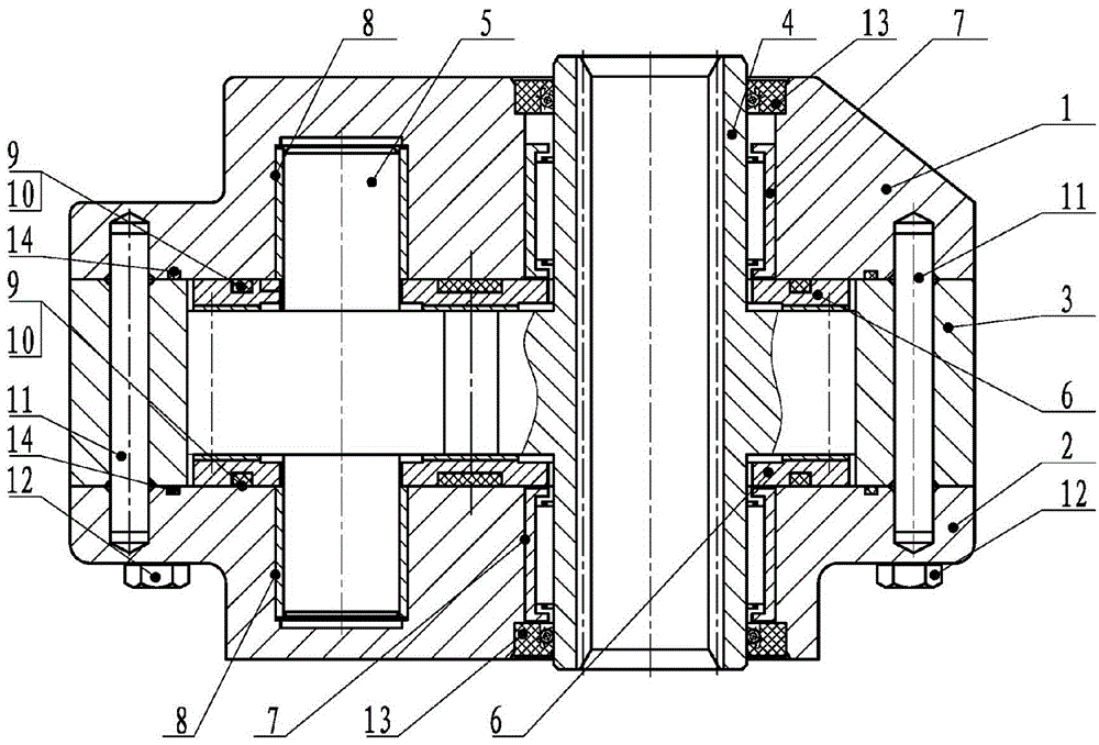
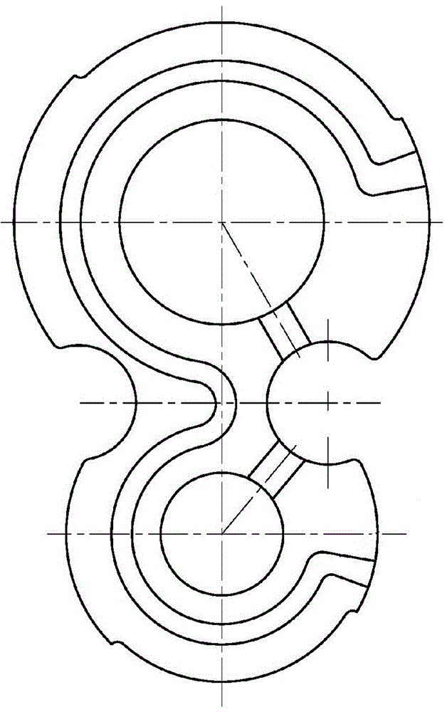
[0018] Such as Figure 1~3 As shown, the present invention includes a pump body 3, a front cover 1 and a rear cover 2 connected to the pump body 3, a pair of gear pairs with different sizes of driving and driven wheels, and two symmetrical floating side plates 6. Among them, there are two roller bearings 7 at the 4 places of the driving wheel, two DU bearings 8 at the 5 places of the driven wheel, a set of E-shaped sealing rings 9 on the back of the floating side plate 6, the pump body 3 and the front cover 1, the pump body 3 and the An outer sealing ring is respectively arranged between the rear covers 2, and the outer sealing ring adopts an O-shaped sealing ring 14 .

[0019] Such as figure 2 As shown, a pair of gear pairs with the same modulus and unequal number of teeth is smaller in size and lighter in weight, and the press...


PUM


Abstract

The invention discloses a large displacement high pressure gear pump with driving and driven wheels in different sizes. A conventional external engaging gear pump is relatively great in flow pulsation, high in noise, low in efficiency and low in pressure. The large displacement high pressure gear pump with driving and driven wheels in different sizes disclosed by the invention comprises a pump body, a front cover and a rear cover connected to the pump body, a pair of gear pairs with driving and driven wheels in different sizes and two symmetrical floating side plates, wherein two roller bearings are arranged at the driving wheel, two DU bearings are arranged at the driven wheel, a set of E-shaped seal ring is arranged on the back of each floating side plate, and an outer seal ring is arranged between the pump body and the front cover and between the pump body and the rear cover, respectively. When the gear pump disclosed by the invention is in a large displacement high pressure operation, the bearing areas of the pump body and the front and back covers are effectively reduced, and the stress environments of parts such as gears, the floating side plates and bearings are greatly improved, so that the working pressure of the gear pump is improved to 1.5 times of that of a common gear pump, the rated working pressure of the gear pump reaches 16MPa and the highest pressure of the gear pump reaches 20MPa.

Description

technical field [0001] The invention relates to a gear pump, in particular to a high-pressure gear pump with a large displacement driving wheel and a driven wheel with different sizes. Background technique [0002] The working principle of the gear pump is as follows: a pair of meshing involute gears with the same parameters and structure are installed inside the housing, and the two ends of the gears are sealed by end covers, so that the two gears are divided into left and right in the housing. Two sealed oil chambers. When the gear rotates in any direction, the teeth of one side of the cavity withdraw from meshing to expose the inter-teeth, so that the volume of the cavity increases to form a partial vacuum to absorb oil. The teeth on the other side of the cavity enter into mesh, and the volume decreases, and the oil between the teeth is gradually squeezed out to complete the oil pressure process. Conventional external gear pumps are simple in structure, and have the cha...

Claims


Application Information

Patent Timeline
Patent Type & Authority Applications(China)
IPC IPC(8): F04C2/18F04C15/00
CPCF04C2/18F04C15/00F04C15/0019F04C2240/30F04C2240/50F04C2240/802
Inventor 阮瑞勇
Owner 江苏国瑞液压机械有限公司
Learn More