Route planning grid space partitioning method for unmanned aerial vehicle

A technology for unmanned aerial vehicle and track planning, which is applied to navigation computing tools and other directions, can solve the problem that track planning cannot meet the requirements of maneuvering constraints, etc., and achieves the effect of saving smooth processing steps, simplifying processes, and saving the consumption of computing resources.

Active Publication Date: 2016-09-21
BEIHANG UNIV
View PDF6 Cites 18 Cited by
  • Summary
  • Abstract
  • Description
  • Claims
  • Application Information

AI Technical Summary

Problems solved by technology

[0006] Therefore, the trajectory planning of unmanned aerial vehicles in the prior art has the problem that the trajectory planning based on the intelligent optimization method cannot meet the maneuver constraint requirements

Method used


Image

  • Route planning grid space partitioning method for unmanned aerial vehicle
  • Route planning grid space partitioning method for unmanned aerial vehicle
  • Route planning grid space partitioning method for unmanned aerial vehicle

Examples


Embodiment 1

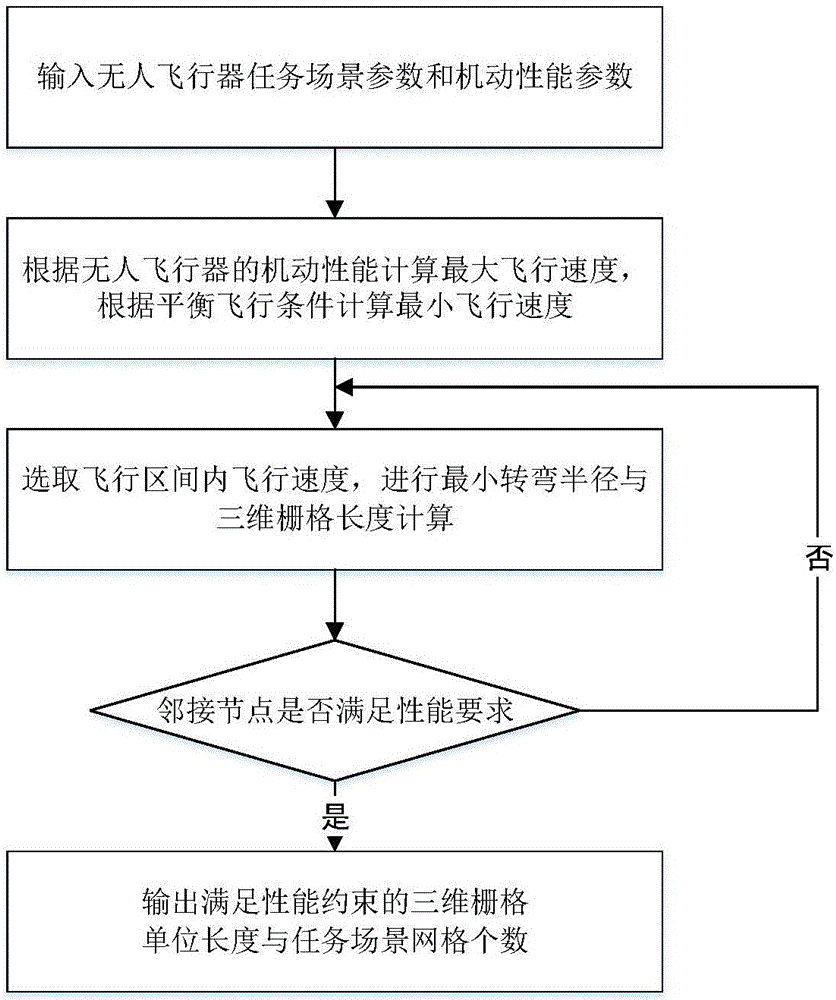
[0076] Example 1: For a small unmanned aerial vehicle flying at an altitude of 500 meters, the grid space division for trajectory planning is performed

[0077] Step 1: Parameter input

[0078] (a) Input the flight altitude H=500m when the unmanned aerial vehicle performs the mission, and the highest terrain height H of the mission scene M =800m;

[0079] (b) Input and UAV parameters, such as UAV reference aerodynamic area S ref =0.5m 2 , UAV head curvature radius R d =0.6m;

[0080] (c) Input the maneuvering parameters of the unmanned aerial vehicle during flight, such as the minimum angle of attack α min =1°, the maximum roll angle φ max =85°, maximum overload n max = 4, maximum normal overload n zmax = 2, coefficient C of overload empirical formula Lα = 2, C D0 =0.055, C Dα =2.5, the maximum aerodynamic pressure q max =5×10 5 Pa and heat flux Q at the maximum stagnation point max =2×10 6 kW / m 2 .

[0081] Step 2: Calculate Safe Flight Speed ​​Corridor

[0...


PUM


Abstract

The invention discloses a route planning grid space partitioning method for an unmanned aerial vehicle. The route planning grid space partitioning method comprises the steps that firstly, the flying height and related maneuvering parameters of the unmanned aerial vehicle in the task executing process and the performance constraint parameters of a vehicle body in the flying process of the unmanned aerial vehicle are obtained; secondly, a safe flying speed passage of the unmanned aerial vehicle under the task flying height is obtained; thirdly, speed partitioning is carried out in the safe flying speed passage, the maximum flying speed is taken, the minimum turning radium and the three-dimensional grid unit length under the maximum flying speed are obtained, and whether a result meets the performance requirement or not is judged; fourthly, the three-dimensional grid unit length meeting performance constraints and the number of three-dimensional grids of a task scene are obtained. According to the route planning grid space partitioning method, grid partitioning meeting maneuvering performance constraints is carried out on the task scene in the task planning stage before high-speed flying of the unmanned aerial vehicle, the minimum turning radius of the unmanned aerial vehicle is determined before route planning, and the smooth processing step after route planning of the unmanned aerial vehicle is omitted.

Description

technical field [0001] The invention relates to the technical field of unmanned aerial vehicle track planning, and is applied to the scene preprocessing stage before unmanned aerial vehicle track planning, in particular to a grid space division method for unmanned aerial vehicle track planning. Background technique [0002] The trajectory planning of the unmanned aerial vehicle is to plan a trajectory with the least cost from the starting point of the unmanned aerial vehicle to support The completion of missions by unmanned aerial vehicles is one of the key technical links in mission planning. [0003] Since the 1950s, unmanned aerial vehicles have been applied to various purposes such as target aircraft and reconnaissance aircraft. With the increasing complexity of missions, the importance of establishing a mission planning system for unmanned aerial vehicles has become increasingly prominent. Track planning is a high-tech developed with modern information technology. [...

Claims


Application Information

Patent Timeline
Patent Type & Authority Applications(China)
IPC IPC(8): G01C21/20
CPCG01C21/20
Inventor 李景文姚锟孙兵谭林
Owner BEIHANG UNIV
Why Eureka
Try Eureka