
Grid successive dissection method used for microseismic positioning

A grid division and microseismic technology, applied in seismology, seismic signal processing, geophysical measurement, etc., can solve problems such as reducing positioning efficiency, increasing computing time, restricting practicability, etc., to improve positioning accuracy, reduce Workload, effect of high microseismic positioning accuracy

Inactive Publication Date: 2016-09-21
JILIN UNIV
View PDF3 Cites 15 Cited by
  • Summary
  • Abstract
  • Description
  • Claims
  • Application Information

AI Technical Summary

Problems solved by technology

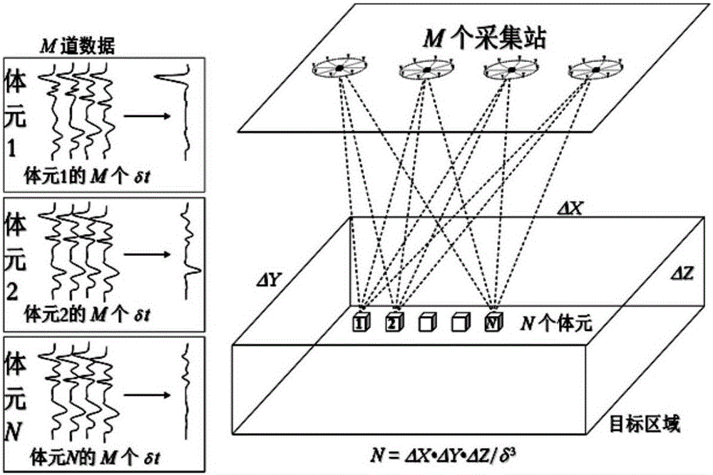
Although the migration microseismic positioning algorithm can overcome the shortcomings of the traditional algorithm, there are still many technical difficulties. For example, the reverse time migration stacking method based on ray theory cannot obtain the analytical solution of the source position, and the subsurface needs to be meshed. , when the grid density is high, the precise location of microseismic events can be achieved
However, when the grid density is increased, the calculation time will be greatly increased, which restricts the practicability of the method
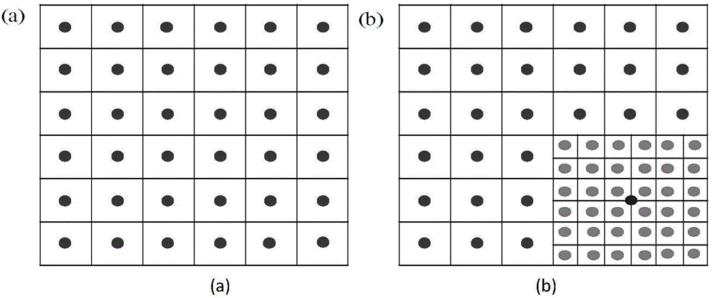
Therefore, when the amplitude offset superposition method is used for perforation positioning, the higher the positioning accuracy, the smaller the grid division size and the higher the density, which greatly increases the calculation amount, resulting in a long calculation time and reducing the positioning efficiency

Method used


Image

  • Grid successive dissection method used for microseismic positioning
  • Grid successive dissection method used for microseismic positioning
  • Grid successive dissection method used for microseismic positioning

Examples


Embodiment 1

[0047] The single-size grid of the original algorithm is used to perform a single global subdivision of the target area. A 5-layer formation model is simulated by computer, and the velocity values ​​of the 1st to 5th layers are as follows:

[0048] 800m / s, 1000m / s, 1700m / s, 2200m / s, 2700m / s, the perforation position is (225, -147, -962), and the simulated seismic waveform is described by 50Hz seismic wavelet.

[0049] A. Define a three-dimensional target area near the perforation, that is, microseismic events may occur in this area. In this embodiment, the target area is selected based on the perforation coordinates. The three-dimensional coordinates of the selected target area are X∈[-300,300], Y∈[-300,300], Z∈[-1000,-800]. The microseismic ground geophones are arranged in a star shape, with a total of 6 survey lines, and each survey line has 16 geophones (96 channels), such as Figure 4 shown. To select one as the reference trace M, it is required that this trace ...

Embodiment 2

[0064] The perforation positioning is carried out by using the method of grid subdivision successively. For the convenience of comparison, the simulation model is the same as that of Example 1, where the velocity values ​​of layers 1 to 5 are: 800m / s, 1000m / s, 1700m / s, 2200m / s, 2700m / s, and the perforation positions are (225 , -147, -962), the simulated seismic waveform is described by 50Hz seismic wavelet.

[0065] A. Define a three-dimensional target area near the perforation, that is, microseismic events may occur in this area. In this embodiment, the target area is selected based on the perforation coordinates. The three-dimensional coordinates of the selected target area are X∈[-300,300], Y∈[-300,300], Z∈[-1000,-800]. The microseismic ground geophones are arranged in a star shape, with a total of 6 survey lines, and each survey line has 16 geophones (96 channels), such as Figure 4 shown. To select one as the reference trace M, it is required that this trace has ...


PUM


Abstract

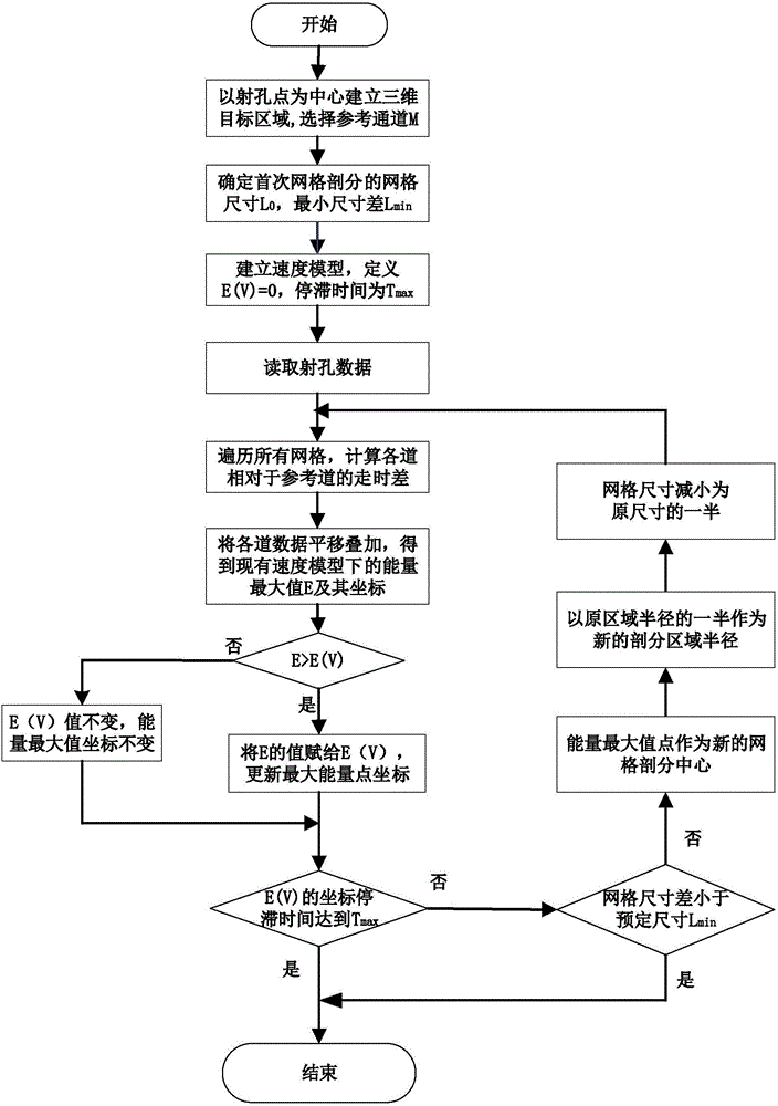
The invention relates to a successive grid subdivision method for microseismic positioning. The method is based on the existing grid search amplitude superposition algorithm. A further subdivision search is carried out near the point to find the global maximum energy focus value, which avoids the global subdivision to improve the positioning accuracy, and obtains higher positioning accuracy with a small calculation cost. The test proves that the present invention effectively solves the problem that the efficiency and calculation accuracy of the existing method are difficult to balance by adopting the perforation positioning method of grid subdivision one by one. Higher microseismic positioning accuracy can be obtained with a lower calculation cost. The global subdivision is avoided, the workload is reduced, and the positioning efficiency is improved under the premise of ensuring the positioning accuracy.

Description

technical field [0001] The invention relates to a microseismic positioning method for oilfield fracturing, specifically, through microseismic monitoring data, on the basis of a grid search amplitude superposition method, a grid subdivision algorithm is used to improve the efficiency of microseismic positioning and precision. technical background [0002] The development of unconventional mineral resources (such as coalbed methane, tight oil, shale oil, etc.) has become a new hot spot in my country and the international oil and gas reservoir industry. Improving the permeability of oil and gas reservoirs through hydraulic fracturing has been widely recognized at home and abroad. Microseismic monitoring is an important part of the hydraulic fracturing process. By accurately locating microseismic events induced by hydraulic fracturing, people can analyze the properties of induced and primary fractures in the ground (geometric characteristics, density, and dimension, etc.) Deli...

Claims


Application Information

Patent Timeline
Patent Type & Authority Applications(China)
IPC IPC(8): G01V1/28
CPCG01V1/288
Inventor 陈祖斌江海宇王金磊王洪超
Owner JILIN UNIV
Learn More