A Piezoelectric Beam Energy Harvester with Axle End Suspension

A wheel-type, piezoelectric beam technology, applied in the direction of piezoelectric effect/electrostrictive or magnetostrictive motors, electrical components, generators/motors, etc., can solve the problem of limited service life, power supply, failure to pass cables, etc. problems, to achieve the effect of high reliability, large power generation, and effective frequency bandwidth

Active Publication Date: 2017-10-10
常州昂德工业装备科技有限公司
View PDF7 Cites 0 Cited by
  • Summary
  • Abstract
  • Description
  • Claims
  • Application Information

AI Technical Summary

Problems solved by technology

[0003] For the monitoring of gears and shafts, the ideal method is to install various sensor monitoring systems on or close to the gears or shafts, so as to realize direct online monitoring of their operating status; It is difficult to popularize and apply the reliable and sufficient power supply for the sensor monitoring system because: ① gears and shafts are in a state of rotating motion and cannot be powered by cables; ② if battery power is used, the battery needs to be replaced frequently due to its limited service life , when the battery power is insufficient and not replaced in time, it will not be able to achieve effective monitoring; ③When the cantilever shaft far away from the bearing seat and its end gear and multiple gears are coaxial, the relative movement between the rotating gear or the shaft and the fixed support cannot be achieved. Constructing Micro Generators
Limited to the energy supply problem of the monitoring system for wind power gearbox gears and shafts, real-time online monitoring in the true sense cannot be realized at present.

Method used


Image

  • A Piezoelectric Beam Energy Harvester with Axle End Suspension
  • A Piezoelectric Beam Energy Harvester with Axle End Suspension
  • A Piezoelectric Beam Energy Harvester with Axle End Suspension

Examples


Embodiment Construction

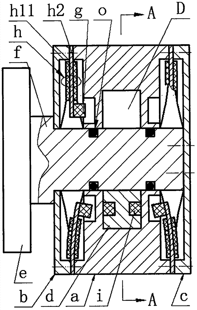
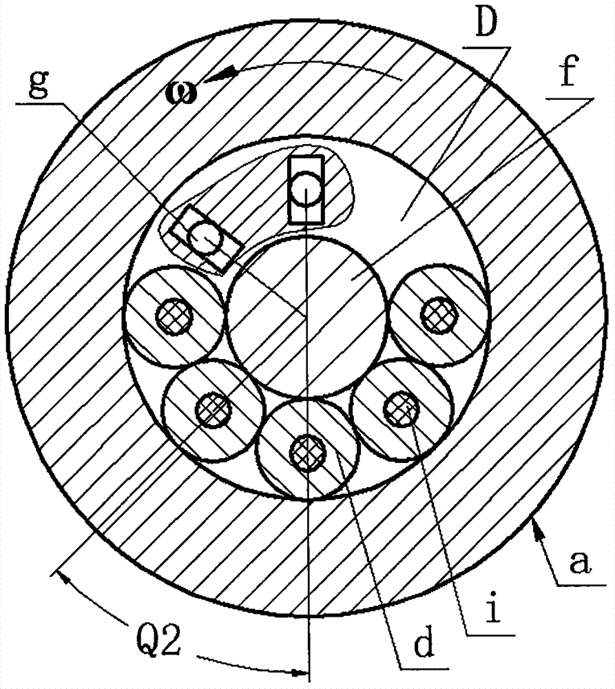
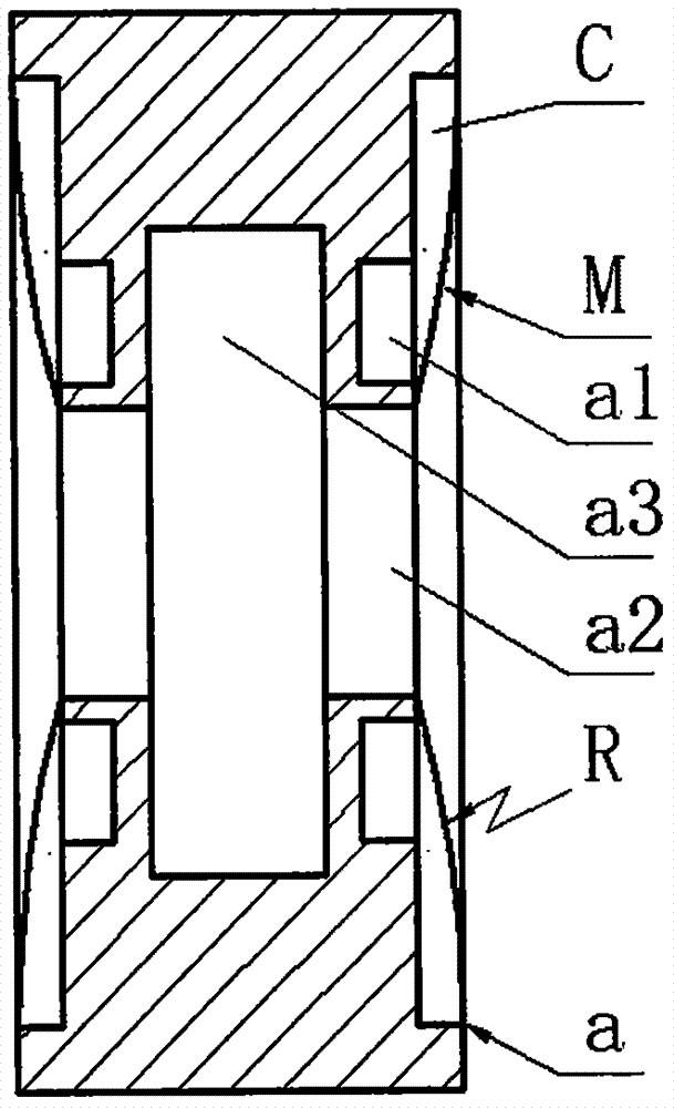
[0016] The left and right end caps b and c are installed on the left and right sides of the runner a respectively through screws, and the metal base h1 is crimped between the left end cover b and the right end cover c and the side wall of the runner a, and the cantilever beam on the metal base h1 h11 and the bonded piezoelectric chip h2 form a piezoelectric vibrator h, the free end of the piezoelectric vibrator h is installed with an excited magnet g through a screw, and the excited magnet g is installed close to the runner a and placed on the rectangular guide on the side of the runner a In the groove a1; the cantilever shaft f of the connector e is placed in the center hole a2 of the runner a and the end is connected with the right end cover c by screws; a sealing ring o is provided between the cantilever shaft f and the center hole a2 of the runner a , the cantilever shaft f and the ring cavity a3 on the runner a form a slideway D, the slideway D is filled with lubricating o...


PUM


Abstract

The invention relates to a runner-type piezoelectric beam energy harvester with a suspended shaft end, and belongs to the field of piezoelectric power generation. A left end cover and a right end cover are arranged at the left side and the right side of a runner respectively; metal substrates provided with cantilever beams are crimped between the left end cover and the side wall of the runner and the right end cover and the side wall of the runner respectively; each metal cantilever beam and an adhered piezoelectric crystal plate form a piezoelectric vibrator; an excited magnet is arranged at a free end of each piezoelectric vibrator, is arranged close to the runner and is arranged in a rectangular guide groove in the side surface of the runner; a cantilever shaft of a gear is arranged in a center hole of the runner and the end part is connected with the right end cover; the cantilever shaft and a ring cavity in the runner form a slideway; a cylindrical exciter made of a non-ferromagnetic material is arranged in the slideway; and exciting magnets are inlaid into two ends of the exciter. The runner-type piezoelectric beam energy harvester with the suspended shaft end has the features and advantages that a fixed support is not needed, the structure is simple and the rotating force on the exciter is small; the piezoelectric vibrators are reasonable in structure and the stresses of various points are the same after deformation; the piezoelectric vibrators are high in generating capacity, high in reliability and wide in effective band; and the runner-type piezoelectric beam energy harvester can be applied to the occasion of coaxial cantilever shaft gear and multi-gear as a standard component.

Description

technical field [0001] The invention belongs to the technical field of new energy and power generation, and in particular relates to a shaft-end-suspended runner-type piezoelectric beam energy harvester, which is used for power supply of a health monitoring system for bearings, shafts and gears of a wind power gearbox. Background technique [0002] The gearbox is a key component of a wind turbine, and its function is to transmit power. When the wind turbine is running normally, the speed of the wind rotor is low, resulting in low efficiency of the generator. Therefore, it is necessary to increase the power generation capacity and efficiency through the gearbox. Because the wind power gearbox works in a variable speed and variable load environment, it is prone to failure; in addition, when the wind power gearbox fails, it is difficult to repair and the cost is high. The operation and maintenance cost of the wind power gearbox can be as high as 30% of the overall operating cos...

Claims


Application Information

Patent Timeline
Patent Type & Authority Patents(China)
IPC IPC(8): H02N2/18
CPCH02N2/18
Inventor 温建明范春涛王淑云阚君武朱雅娜
Owner 常州昂德工业装备科技有限公司
Why Eureka
Try Eureka