Realization method of improved server control electric current loop PI regulator

A technology of servo control and implementation method, which is applied to control electromechanical brakes, control generators, control electromechanical transmissions, etc., and can solve problems such as gain overshoot and oscillation, asynchronous timing of control and feedback, and impact on stability.

Inactive Publication Date: 2016-09-21
YANGTZE DELTA REGION INST OF TSINGHUA UNIV ZHEJIANG
View PDF3 Cites 0 Cited by
  • Summary
  • Abstract
  • Description
  • Claims
  • Application Information

AI Technical Summary

Problems solved by technology

[0003] At present, the control method of PI regulator is generally used to adjust the input and output of the current loop. Increasing the proportional gain can improve the response speed, but if the gain is too large, it will cause overshoot and oscillation, which will affect the stability.
Moreover, this control method is base...

Method used


Image

  • Realization method of improved server control electric current loop PI regulator
  • Realization method of improved server control electric current loop PI regulator
  • Realization method of improved server control electric current loop PI regulator

Examples


Embodiment Construction

[0015] The permanent magnet synchronous motor is a complex nonlinear system. Space vector transformation is usually used to simplify its mathematical model. The voltage equation in the synchronous rotating coordinate system is:

[0016]

[0017]

[0018] In the formula: u d , u q is the voltage of stator d, q axis; i d i q Respectively, the stator d, q axis current; R is the stator resistance; L d , L q is the stator d, q axis inductance; ω is the rotor electrical angle; ψ f is the permanent magnet flux linkage.

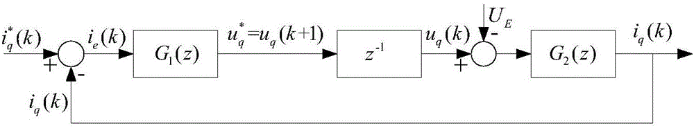
[0019] The block diagram of the current loop control controlled by the traditional PI regulator is as follows: figure 1 As shown, in a traditional PI regulator, the output of the regulator It needs to be delayed by one cycle to be applied, that is, in the next cycle with u q (k+1) is applied to the motor. u q (k+) and the voltage u being applied in the current cycle q The difference in (k) lies in the lag of one cycle, which is equivalent to ignorin...


PUM


Abstract

The invention discloses a realization method of an improved server control electric current loop PI regulator. The method is characterized in that a correction step is added after that the PI regulator outputs Uq<*> and before that a voltage Uq(k+1) is applied to a motor in a next period, and the correction step comprises 1/(1+z<-1>) concretely. According to the invention, advantages of an original traditional PI regulator are maintained, the improved PI regulator is provided by considering the problem that control controlled variable and the feedback variable are not synchronous sequentially, sequential asynchronism is eliminated, overshooting and oscillation are avoided in the control process, the dynamic performance of the system is improved, and the stable domain of PI parameters is broadened.

Description

technical field [0001] The invention relates to a current loop PI regulator, in particular to a realization method of an improved servo control current loop PI regulator. Background technique [0002] At present, most permanent magnet synchronous servo systems adopt all-digital control, and the main control process is sampling, calculation, and duty cycle update, so as to adjust the system output. The specific process is that the error of the input and output is obtained by sampling, and then the control amount is obtained through the calculation of the regulator, and updated into the duty cycle to calibrate the error. [0003] At present, the control method of PI regulator is generally used to adjust the input and output of the current loop. Increasing the proportional gain can improve the response speed, but if the gain is too large, it will cause overshoot and oscillation, which will affect the stability. Moreover, this control method is based on the feedback error obtai...

Claims


Application Information

Patent Timeline
IPC IPC(8): H02P21/00H02P21/22
CPCH02P21/0003
Inventor 徐本亮史加悦王利峰缪惠根潘丽杰
Owner YANGTZE DELTA REGION INST OF TSINGHUA UNIV ZHEJIANG
Why Eureka
Try Eureka