Composite function single-cycle control system and method of power electronic power converter
A single-cycle control and power converter technology, which is applied in the direction of control/regulation system, DC power input conversion to DC power output, output power conversion device, etc., can solve problems such as inability to control bifurcations, and achieve good practical value. The effect of expanding the stable domain and simplifying the structure
- Summary
- Abstract
- Description
- Claims
- Application Information
AI Technical Summary
Problems solved by technology
Method used
Image
Examples
Embodiment 1
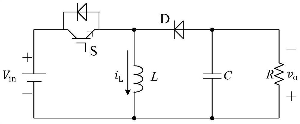
[0040] Taking the Buck-Boost converter as an example, the control method of a compound function single-cycle control system for a power electronic power converter disclosed in the present invention will be further described in detail in conjunction with the accompanying drawings.
[0041] The main circuit part of the Buck-Boost converter is as follows: figure 1 shown. figure 1 Include the input voltage u in, Switching tube S, diode D, load resistor R, T are switching cycles, inductance L and filter capacitor C. where the inductor current with i L Indicates that the output voltage u o Use to express.
[0042] Taking the circuit inductor current i L and output voltage v o For the state variable x=[u o i L ] T , the state equation of the Buck-Boost converter is established from the operating state of the circuit (two states: the switch tube is on and the switch tube is off):
[0043]
[0044] in
[0045] Use d to represent the switching duty cycle of the Buck-Boo...
Embodiment 2
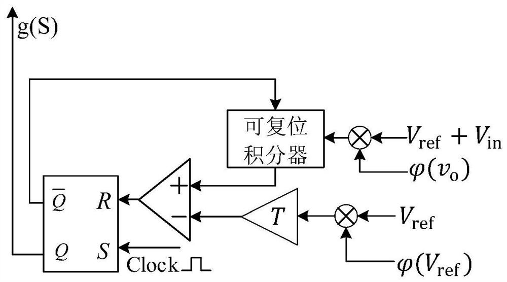
[0054] This embodiment discloses a complex function single-cycle control system of a power electronic power converter based on a Buck-Boost converter, figure 2 Shown is a composite function single-cycle control system structure diagram. The control system includes: a detection unit, a complex function unit, a multiplier, a reset integrator, a comparator, and an RS flip-flop. The detection unit is directly connected to the external Buck-Boost converter, and the output voltage u of the Buck-Boost converter is detected o , the detected signal is sent to the composite function unit and sent to the reset integrator after passing through the multiplier; at the same time, the reference voltage u ref Send to the compound function unit and get the reference value after passing through the multiplier The reset integrator processes the received signal, and then sends the obtained signal and reference value to the comparator. The output terminal of the comparator is connected to the R...
Embodiment 3
[0056] This embodiment discloses a control method of a composite function single-cycle control system based on a Buck-Boost converter. The control method is based on figure 2 The control system used in the Buck-Boost converter is implemented. The specific workflow of the method is as follows: at the beginning of a cycle, such as the kth switching cycle, firstly, the signal u ref The reference is calculated through the composite function unit and the multiplier value, the output of the integrator is reset to zero at this time. When the clock signal is at a high level, the RS flip-flop is triggered, and the switch S is turned on through its Q terminal. At this time, the integrator pair is reset. Integrating, the output value increases monotonically from the initial value. When the output value of the reset integrator is greater than the reference value, the output terminal of the comparator will generate a reset pulse signal to reset the reset integrator, and the Q terminal...
PUM
 Abstract
Description
Claims
Application Information
 - R&D
- Intellectual Property
- Life Sciences
- Materials
- Tech Scout
- Unparalleled Data Quality
- Higher Quality Content
- 60% Fewer Hallucinations
Browse by: Latest US Patents, China's latest patents, Technical Efficacy Thesaurus, Application Domain, Technology Topic, Popular Technical Reports.
© 2025 PatSnap. All rights reserved.Legal|Privacy policy|Modern Slavery Act Transparency Statement|Sitemap|About US| Contact US: help@patsnap.com


