A kind of gold-finger gold-plated lead wire adding method

A gold-plated lead wire and gold finger technology, which is applied in the field of gold-plated lead wire addition, can solve problems such as low work efficiency, many steps of human judgment, and error-prone, so as to improve work efficiency, avoid manual adding errors, and reduce human judgment.

Active Publication Date: 2018-06-22
GUANGZHOU FASTPRINT CIRCUIT TECH +2
View PDF6 Cites 0 Cited by
  • Summary
  • Abstract
  • Description
  • Claims
  • Application Information

AI Technical Summary

Problems solved by technology

However, it has the following defects: in the process of manually adding gold-plated leads to the gold fingers, since the gold fingers are widely distributed on the top, bottom and side of the circuit pattern, it is necessary to make the top, bottom and side circuit layers according to the type of gold fingers during CAM production. Manually add gold-plated leads to the gold fingers one by one. There are many steps of human judgment, which is error-prone, time-consuming and low in work efficiency.

Method used


Image

  • A kind of gold-finger gold-plated lead wire adding method
  • A kind of gold-finger gold-plated lead wire adding method
  • A kind of gold-finger gold-plated lead wire adding method

Examples


Embodiment 1

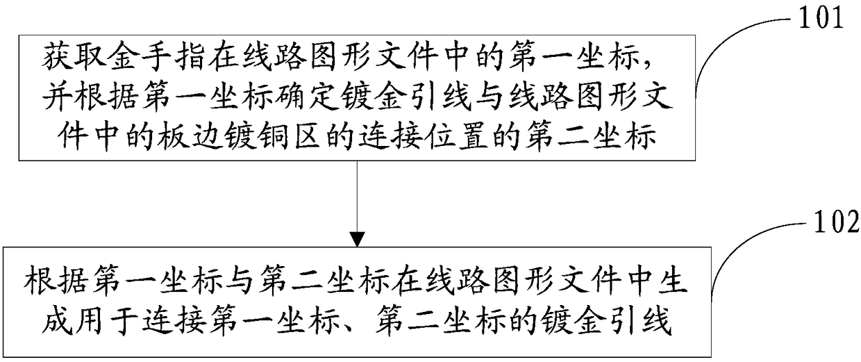
[0027] Such as figure 1 , 3 And shown in 4, golden finger gold-plated lead wire adding method of the present invention, comprises the steps:

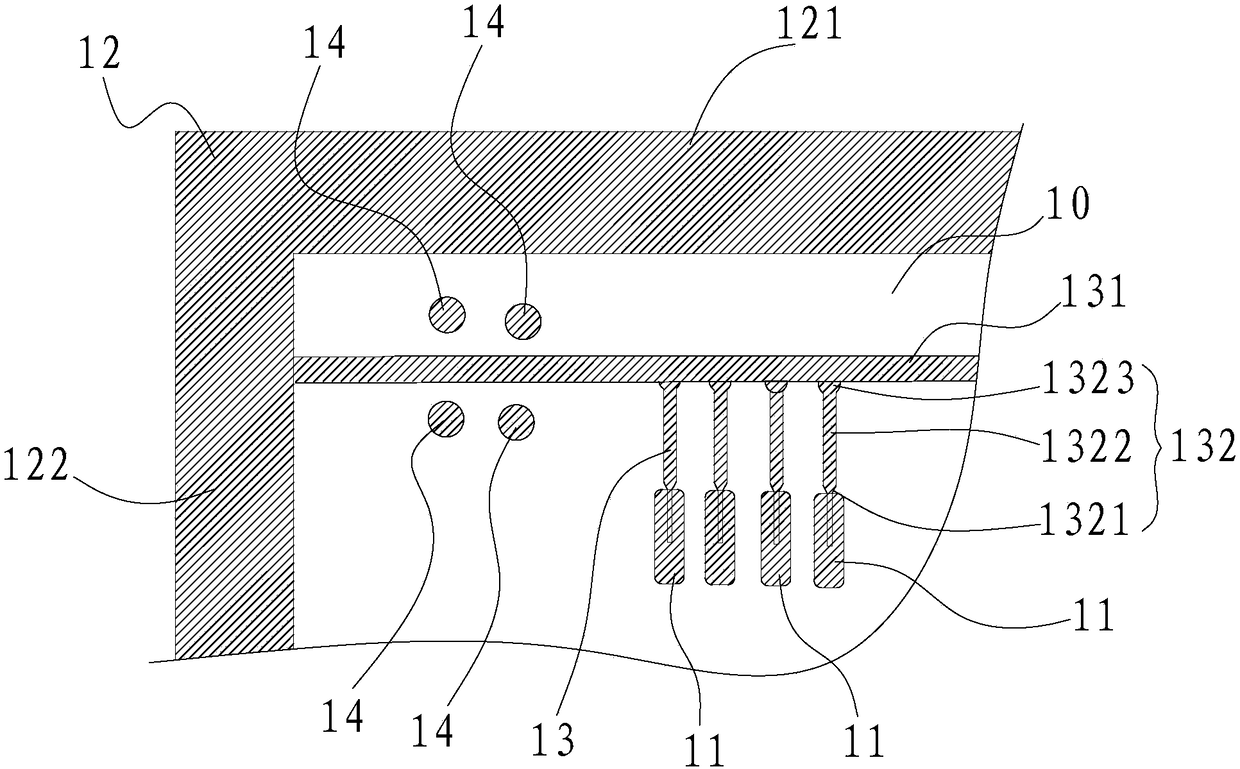
[0028] Step S101, after the gold finger 11 in the circuit graphic file 10 is successfully added, obtain the first coordinates of the gold finger 11 in the circuit graphic file 10, and determine the relationship between the gold-plated lead 13 and the The second coordinate of the connection position of the board edge copper plating area 12 in the circuit pattern file 10;

[0029] Step S102 , generating the gold-plated leads 13 for connecting the first coordinates and the second coordinates in the line graphic file 10 according to the first coordinates and the second coordinates.

[0030] The above-mentioned gold-finger gold-plated lead adding method automatically generates gold-plated lead 13 in the circuit graphic file 10 according to the coordinates of the gold finger 11 in the circuit graphic file 10, without manually adding it in t...

Embodiment 2

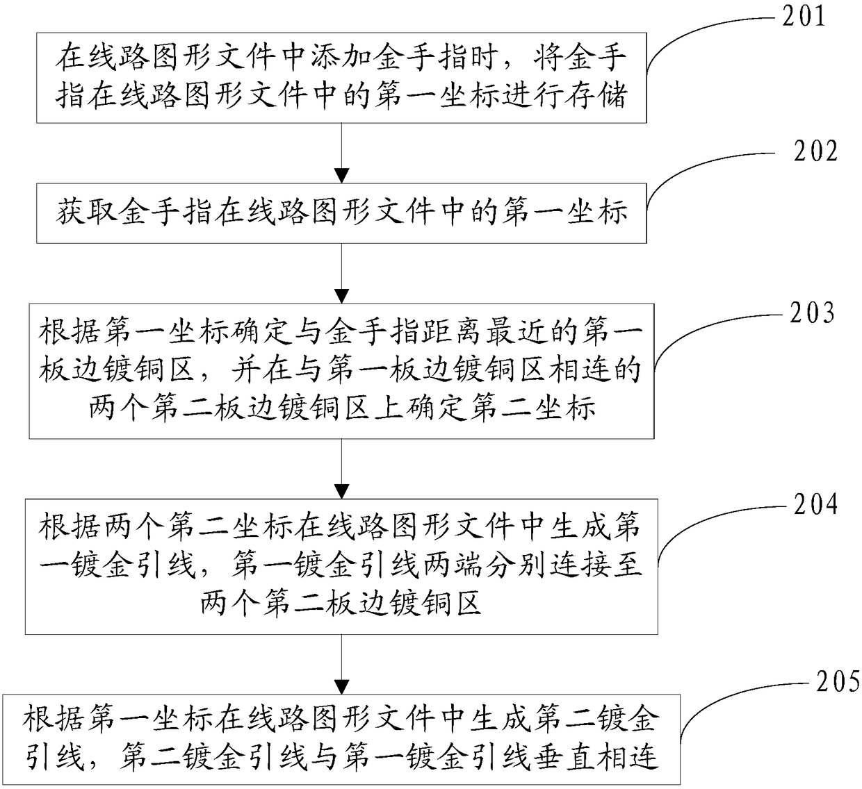
[0032] see figure 2 , 3 And 4, gold finger gold-plated lead wire adding method of the present invention, comprises the steps:

[0033] Step S201, when adding the golden finger 11 in the circuit graphic file 10, storing the first coordinates of the cheat 11 in the circuit graphic file 10;

[0034] Step S202, after the gold finger 11 in the line graphic file 10 is successfully added, obtain the first coordinate of the cheat 11 in the line graphic file 10;

[0035] Step S203: Determine the first board edge copper plating area 121 closest to the gold finger 11 according to the first coordinates, and plate two second board edge copper plating areas 121 connected to the first board edge determining the second coordinates on the copper zone 122;

[0036] Step S204, generating the first gold-plated leads 131 in the circuit graphics file 10 according to the two second coordinates, and the two ends of the first gold-plated leads 131 are respectively connected to two copper-plated ed...


PUM


Abstract

The invention discloses a gold-plating lead adding method for golden fingers. The gold-plating lead adding method comprises the following steps: after the golden fingers in a circuit graphic file are added successfully, obtaining the first coordinates of the golden fingers in the circuit graphic file, and determining the second coordinates of connecting positions of gold-plating leads and plate edge copper-plating areas in the circuit graphic file according to the first coordinates; and generating the gold-plating leads for connecting the first coordinates and the second coordinates in the circuit graphic file according to the first coordinates and the second coordinates. According to the gold-plating lead adding method for the golden fingers, the gold-plating leads are automatically generated in the circuit graphic file according to the coordinates of the golden fingers in the circuit graphic file, and that leads are manually added in the circuit graphic file in the prior art is not needed. In this way, when the circuit graphic file is manufactured, artificial judgment is reduced, errors caused by manual addition are avoided, and the gold-plating leads are conveniently added to the golden fingers, so that the work efficiency is improved.

Description

technical field [0001] The invention relates to the technical field of gold finger production, in particular to a gold finger gold-plated lead adding method. Background technique [0002] When CAM production personnel make gold finger type orders, they need to manually add gold-plated leads to the gold finger after the PNL edge sealing is completed. However, it has the following defects: in the process of manually adding gold-plated leads to the gold fingers, since the gold fingers are widely distributed on the top, bottom and side of the circuit pattern, it is necessary to make the top, bottom and side circuit layers according to the type of gold fingers during CAM production. Manually add gold-plated leads to the gold fingers one by one. There are many steps of human judgment, which is error-prone, time-consuming and low in work efficiency. Contents of the invention [0003] Based on this, the present invention overcomes the defects of the prior art and provides a metho...

Claims


Application Information

Patent Timeline
Patent Type & Authority Patents(China)
IPC IPC(8): H05K3/00G06F17/50
CPCG06F30/39H05K3/0005H05K2201/09409
Inventor 朱荣坤王伟烨邓智河
Owner GUANGZHOU FASTPRINT CIRCUIT TECH
Why Eureka
Try Eureka