Device for treating or machining a surface

A technology for surface processing and surface treatment, which is applied in the field of devices for surface treatment or surface processing, and can solve problems such as large measurement errors

Inactive Publication Date: 2016-09-21
ZS HANDLING
View PDF15 Cites 8 Cited by
  • Summary
  • Abstract
  • Description
  • Claims
  • Application Information

AI Technical Summary

Problems solved by technology

However, a measuring system arranged far away from the actuator produces greater measurement errors than a measuring system arranged directly at the actuator

Method used


Image

  • Device for treating or machining a surface
  • Device for treating or machining a surface
  • Device for treating or machining a surface

Examples


Embodiment Construction

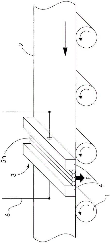
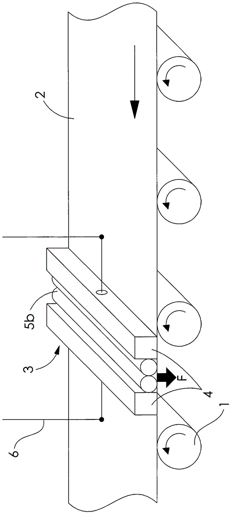
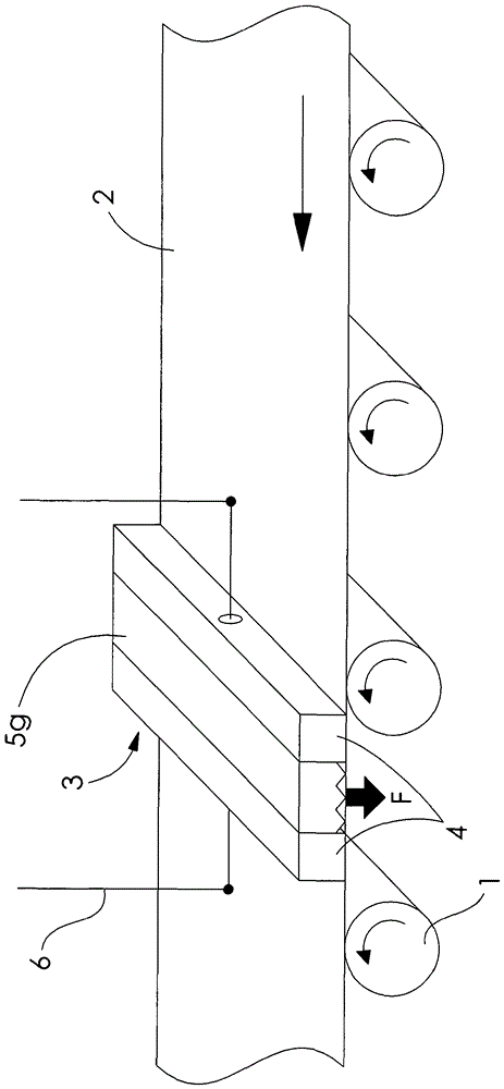
[0034] picture 1 schematically shows Device for spraying oil. The strip material to be sprayed, such as for example sheet metal, passes over driven rollers 1 be guided. in work unit 3 Contains Ultrasonic Oscillator Module 4 and spray nozzles 5a . The ultrasonic oscillation module 4 on its underside and on the surface of the strip material 2 ultrasonic waves - Levitation Field ( Ultraschall-Levitationskraftfeld ). The unit of work 3 hanging on a movable suspension 6 and is pressed onto the strip material based on its own weight, that is to say in this example gravity is applied as the pressing mechanism ( Draengmittel ), but mechanical springs or other equivalently acting mechanisms can also be used. through the ultrasonic - suspend - The force field creates a reaction force such that the working cell 3 suspended over the surface of the strip material at a previously determined distance 2 superior. This distance can be adj...


PUM


Abstract

The invention relates to a device for treating or acting on workpiece surfaces by means of an actuator, such as a cutting or engraving laser or a nozzle for applying oils, paints, adhesives, dyes, or etchants for example. In particular, the invention relates to a device which is suitable for acting on workpieces with relatively large surfaces relative to the dimensions of the actuator, such as on strip materials for example. An ultrasonic levitation force field is generated by means of a sonotrode (4), which is coupled to the actuator into a working unit (3), such that the movably suspended working unit (3) is supported on the workpiece surface in a hovering manner. The ultrasonic levitation force field allows a highly precise positioning of the working unit (3) relative to the workpiece surface so as to allow a precise treatment or machining of the workpiece surface.

Description

technical field [0001] The invention relates to devices for treating or acting on workpiece surfaces by means of actuators, such as lasers for cutting or engraving, nozzles for applying oils, lacquers, adhesives, pigments, etchants, release agents, etc. device. The invention relates in particular to a device which is suitable for acting on workpieces having a relatively large surface—relative to the size of the actuator—such as, for example, strip material. Background technique [0002] Systems are known from the prior art which enable an accurate calibration of the working area of ​​an actuator in the x-, y- and z-directions with respect to the workpiece surface. For example, a beam is used for calibrating actuators in the x-y direction, which beam is coupled to a length measuring device. Such systems are hereinafter referred to as linear drives. [0003] Depending on the course of the surface treatment or the effect of the treatment on the surface, different degrees of ...

Claims


Application Information

Patent Timeline
Patent Type & Authority Applications(China)
IPC IPC(8): B23K26/38B23K26/046B23K26/60
CPCB23K26/60B23K26/048B23K26/38B05B13/0278B05C5/0295B05C19/04G10K15/00B08B7/028H01J37/3277B23K20/10B23K26/083B23K26/40B23K26/361B23K2101/16B23K2103/50B23K26/352B23K26/362B23Q1/38G01N21/25G01N27/02G01N27/22
Inventor M.希尔普J.齐默曼A.齐茨曼
Owner ZS HANDLING
Why Eureka
Try Eureka