Machine tool with spindle tool holder

A turning tool holder and spindle technology, which is applied to metal processing mechanical parts, large fixed members, metal processing equipment, etc., can solve the problems of difficult high-speed rotation of the cutter head, large X-direction travel of the machine base, and large investment in site area. Achieve the effect of increasing the utilization rate of the cloth knife, improving the indexing and positioning accuracy, and reducing the time for changing the knife

Active Publication Date: 2016-09-28
GUANGZHOU WEIJIA MACHINE
View PDF7 Cites 9 Cited by
  • Summary
  • Abstract
  • Description
  • Claims
  • Application Information

AI Technical Summary

Problems solved by technology

[0002] Traditionally, there are two main processing methods for slender parts that require hexagonal or square turning and rough and fine turning of the outer circle: the first processing method, first rough and fine Turn the outer circle of the workpiece, and then process it on another lathe square bed; this processing method has the disadvantages of low processing efficiency, high investment cost, and large investment in site area
The second processing method is to use a row tool type lathe with a tailstock for processing, such as a square tool holder or a turret or a rough and fine composite turning tool holder with a turning spindle. It is required that the X-direction stroke of the machine base is relatively large
[0003] In addition, the traditional turning tool post mainly uses the motor servo and the gear deceleration to drive the cutter head to rotate, and realizes the circumferential direction of the tool through a pair of comb teeth (one is fixed on the base body and the other is on the rotating cutter head). Indexing and radial positioning, and this driving method is difficult to make the cutter head rotate at a high speed, and this method achieves the final positioning through a pair of comb teeth, which has a great impact on the machining accuracy and processing technology of the comb teeth high requirements
For processed items that are difficult to process and require high precision, it is difficult to achieve arbitrary radial positioning through the comb plate

Method used


Image

  • Machine tool with spindle tool holder
  • Machine tool with spindle tool holder
  • Machine tool with spindle tool holder

Examples


Embodiment 1

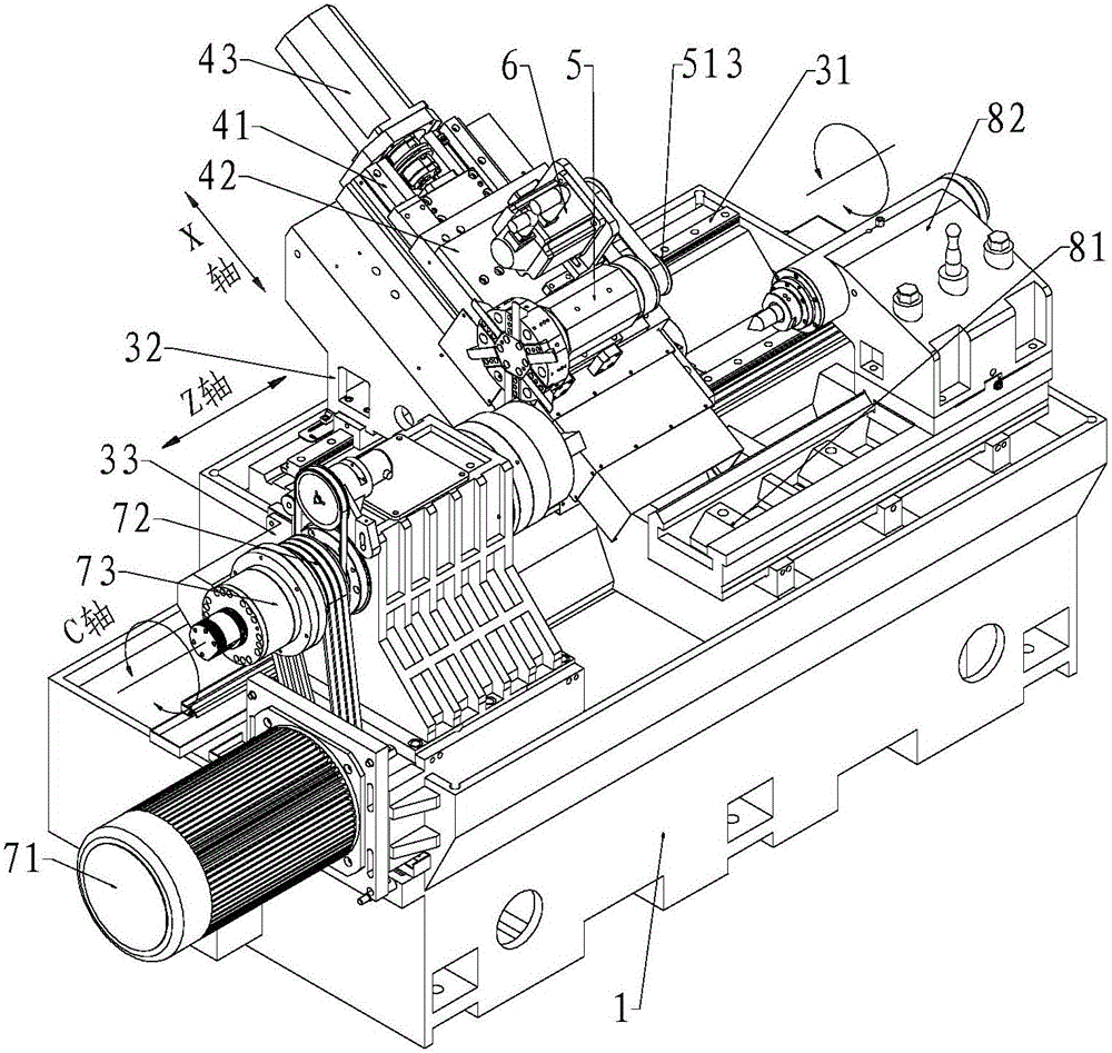
[0039] refer to Figure 1-Figure 5 , a machine tool with a spindle turning tool holder described in this embodiment, including a machine base 1, a Z guide rail 31, an inclined bed 32, a Z direction motor 33, an X guide rail 41, and an X guide rail 31 on the machine base 1 To the slide plate 42, the X-direction motor 43, the spindle turning tool rest 5 and the spindle turning tool rest driving motor 6; the upper surface of the inclined bed 32 is an inclined surface, and the inclined bed 32 is installed on the Z guide rail 31, and is guided by Z Drive the inclined bed 32 to the motor 33 to slide on the Z guide rail 31; the X guide rail 41 is installed on the inclined bed 32, the X slide plate 42 is installed on the X guide rail 41, and the X direction is driven by the X direction motor 43. The slide plate 42 slides on the X-guiding rail 41; the spindle turning tool rest 5 is installed on the X-direction sliding plate 42 of the inclined bed 32, and the spindle turning tool rest 5...

Embodiment 2

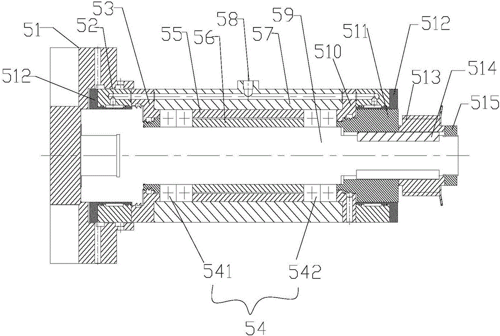
[0056] The difference between this embodiment and Embodiment 1 is that a hydraulic oil inlet 58 is arranged on the upper surface of the box body 57, and an oil pipeline is installed inside the box body 57, and the oil inlet 58 of the hydraulic oil is connected with the oil pipeline, and the oil pipeline is connected with the oil pipeline. The oil inlet pipelines 516 of the front brake 52 and the rear brake 512 are both connected. The hydraulic oil enters the oil inlet pipeline 516 from the oil inlet 58 of the box body 57, and then reaches the annular hydraulic chamber 519 to elastically deform the diaphragm 520 in the brake assembly, and then use the elastic deformation of the diaphragm 520 to make the brake assembly Hold the main shaft 59 and the locking spacer 511 tightly along the circumference of the inner hole of the diaphragm 520 to achieve accurate positioning.

Embodiment 3

[0058] The feature of this embodiment is that: no Z-direction rail and Z-direction motor are arranged on the machine base. The inclined bed is fixedly installed on the machine base; others are the same as in Embodiment 1.


PUM


Abstract

The invention discloses a machine tool with a spindle tool holder. The machine tool comprises a machine seat. An oblique lathe bed, an X-direction guide rail, an X-direction sliding plate, an X-direction motor, the spindle tool holder and a spindle tool holder drive motor are arranged on the machine seat. The X-direction motor drives the X-direction sliding plate to slide on the X-direction guide rail. The spindle tool holder drive motor drives the spindle tool holder to rotate. A workpiece spindle motor, a workpiece spindle transmission mechanism and a workpiece spindle are arranged on the portion, on the left side of the oblique lathe bed, of the machine seat. A tailstock sliding rail, a tailstock and a tailstock drive motor are arranged on the portion, on the right side of the oblique lathe bed, of the machine seat. The brand-new spindle tool holder is designed, row tools on the machine seat are reduced, the use rate of distributed tools of a cutterhead is increased, the stroke of the machine seat is reduced, and machining efficiency is improved.

Description

technical field [0001] The invention relates to a machine tool, in particular to a machine tool with a spindle turning tool holder, which belongs to the technical field of machine bases. Background technique [0002] Traditionally, there are two main processing methods for slender parts that require hexagonal or square turning and rough and fine turning of the outer circle: the first processing method, first rough and fine Turn the outer circle of the workpiece, and then process it on another lathe square bed; this processing method has the disadvantages of low processing efficiency, high investment cost, and large investment in site area. The second processing method is to use a row tool type lathe with a tailstock for processing, such as a square tool holder or a turret or a rough and fine composite turning tool holder with a turning spindle. The X-direction travel of the base is required to be larger. [0003] In addition, the traditional turning tool post mainly uses t...

Claims


Application Information

Patent Timeline
Patent Type & Authority Applications(China)
IPC IPC(8): B23B21/00B23Q5/34
CPCB23Q1/26B23Q5/34
Inventor 赵虎谢政平党军朋
Owner GUANGZHOU WEIJIA MACHINE
Why Eureka
Try Eureka