
A spherical cabin and its forming method

A molding method and a technology of a spherical cabin, which can be used in aerospace equipment, simulators of space navigation conditions, instruments, etc., can solve problems such as complex costs, and achieve the effects of economical processing costs, convenient manufacturing, and high crack resistance

Inactive Publication Date: 2019-04-16
成都泛美视界科技有限公司
View PDF8 Cites 0 Cited by
  • Summary
  • Abstract
  • Description
  • Claims
  • Application Information

AI Technical Summary

Problems solved by technology

[0004] In view of the deficiencies in the above-mentioned prior art, the purpose of the present invention is to provide a spherical cabin and its forming method to solve the problem of high complexity and high cost of the traditional process

Method used


Image

  • A spherical cabin and its forming method
  • A spherical cabin and its forming method
  • A spherical cabin and its forming method

Examples


Embodiment 1

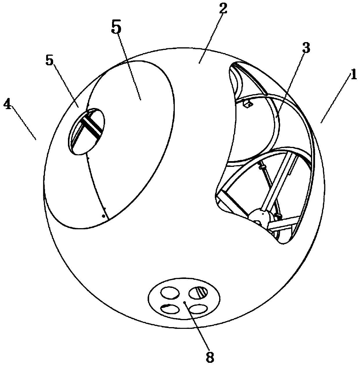
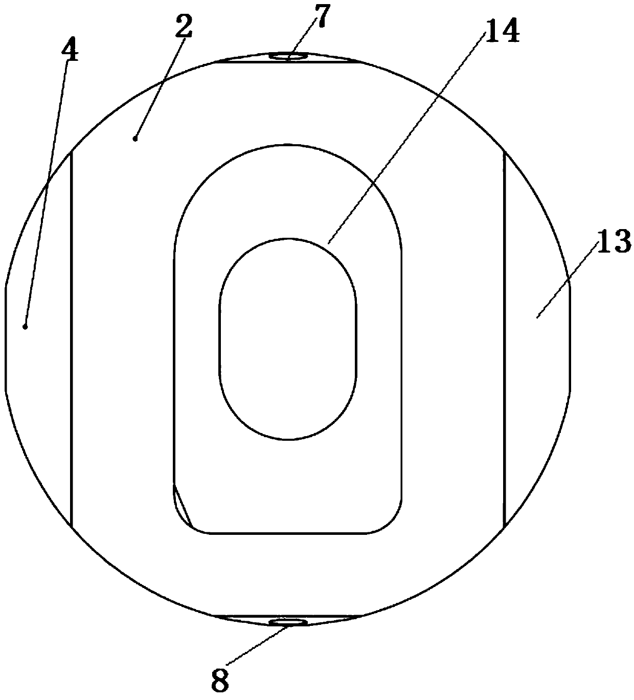
[0022] Embodiment 1: comprising a spherical drum-shaped main body 1, the drum-shaped main body 1 includes a shell 2 and a frame 3, the shell 1 is wrapped on the outer surface of the frame 2, and the left and right sides of the shell 2 are respectively provided with a second A crescent-shaped component group 4 and a second crescent-shaped component group 13, the first crescent-shaped component group 4 and the second crescent-shaped component group 13 are respectively welded on the shell 2, and the front side of the shell 2 is provided with a hatch 14 , the frame 3 is welded by reinforcing ribs 11, angle steels 12, channel steels and spokes 10 in the cabin.

[0023] The first crescent-shaped component group 4 includes two round pot-shaped first crescent components 5 assembled and welded, and the second crescent-shaped component group 13 includes two round pot-shaped second crescent components assembled and welded. A first hub 9 and a second hub 15 are respectively formed on the ...

Embodiment 2

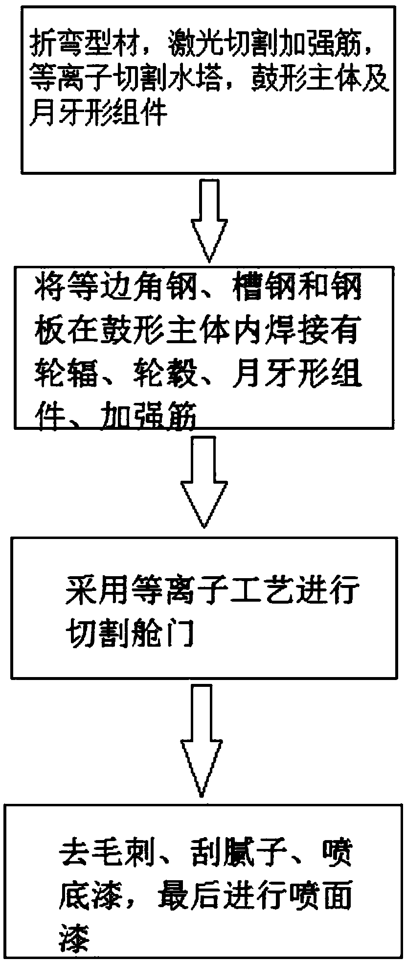
[0029] Embodiment 2: first select some spherical water towers as the main body of the spherical cabin and equilateral angle steel, channel steel and steel plate as auxiliary components, then cut and trim the edges, and equilateral angle steel, channel steel and steel plate are welded in the drum-shaped main body. Spokes, hubs, crescent-shaped components, and stiffeners complete the basic structure of the spherical cabin. Finally, the plasma process is used to cut the hatch; deburring, puttying, primer spraying, and finally spraying topcoat.

[0030] The reinforcing rib of the crescent-shaped component is made of 3mm thick steel plate with a width of 35mm, all of which are formed by laser cutting; the runout of the projected circle in any direction shall not exceed 10mm; the concentricity of the two hubs shall not be less than 2mm, which must be guaranteed by welding tooling), and reinforcing ribs.

[0031] Due to the adoption of the above technical solution, the present invent...


PUM

PropertyMeasurementUnit
thicknessaaaaaaaaaa
widthaaaaaaaaaa
thicknessaaaaaaaaaa

Abstract

The invention relates to the technical field of simulator accessories, in particular to a high-efficiency and low-cost economical type spherical cabin and a molding method thereof. The spherical cabin comprises a spherical drum type main body, wherein the drum type main body comprises a shell and a framework, the shell is arranged on the outer surface of the framework in a sleeving manner, and crescent component groups are separately arranged on the left and right sides of the shell. The method comprises: bending sectional materials, cutting reinforcing ribs by using laser, and cutting a water column, the drum type main body and crescent components by using plasma arcs; using equilateral angle steels, channel steels and steel plates to weld spokes, a hub, the crescent components and the reinforcing ribs in the drum type man body, and cutting a cabin door by adopting a plasma technology; and removing burrs, applying putty, spraying a priming paint and finally spraying a finish paint. The molding method enables the cabin body to run more stably, and the spherical cabin is simple in technology, is great in stress by adopting an arc-shaped structure, is economical in processing cost, is high in crack resistance, is high in connecting strength due to the adoption of plasma cutting and carbon dioxide protection, is simple in structure, is convenient to produce and manufacture, and at the same time, has high practicability.

Description

technical field [0001] The invention relates to the technical field of simulator accessories, in particular to a spherical cabin and a forming method thereof. Background technique [0002] In a broad sense, a flight virtual simulator is a machine used to simulate the flight of an aircraft. Devices that simulate the flight of airplanes, missiles, satellites, spacecraft, etc. can be called flight simulators. It is a simulation device that can reproduce the aircraft and the air environment and can be operated. In a narrow sense, it is a device that is used to simulate the flight of an aircraft and has a relatively complex structure and relatively complete functions. If it is a flight simulation device with a relatively simple structure and few functions, it is called a flight training device. The use of flight virtual simulators for flight training has the advantages of improving training efficiency, saving training funds, ensuring flight safety, and reducing environmental p...

Claims


Application Information

Patent Timeline
Patent Type & Authority Patents(China)
IPC IPC(8): B23P15/00G09B9/08
CPCB23P15/00G09B9/08
Inventor 李焱昭罗哲冯海均段兵
Owner 成都泛美视界科技有限公司
Learn More