Engine exhaust cooler

A cooler and engine technology, which is applied to engine components, machines/engines, exhaust devices, etc., can solve the problems of large changes in heat transfer coefficient, reduction of heat transfer power of coolers, and different heat transfer coefficients of heat exchange tubes. Achieve the effect of increasing heat transfer coefficient, reducing pressure loss and increasing heat transfer power

Inactive Publication Date: 2016-09-28
ZHEJIANG UNIVERSITY OF SCIENCE AND TECHNOLOGY
View PDF5 Cites 3 Cited by
  • Summary
  • Abstract
  • Description
  • Claims
  • Application Information

AI Technical Summary

Problems solved by technology

[0002] Due to the existence of tube bundles, the tube bundle gas cooler divides the interior of the cooler into different areas, resulting in different gas flow states in different areas, and thus different heat transfer intensities in different areas; when the gas to be cooled traverses the tube bundle, the exchange The heat transfer coefficient of the heat pipe circle varies greatly, and the maximum heat transfer coefficient in the area around the heat exchange tube is 2 to 3 times the minimum heat transfer coefficient. This uneven distribution of heat transfer coefficient seriously reduces the average heat exchange tube bundle. The heat transfer coefficient reduces the heat transfer power of the cooler. In order to achieve a certain cooling effect, the gas cooler needs to consume more materials, so the gas cooler has a larger volume and a higher price; improve the heat transfer of the gas cooler Strength, reducing the volume of the gas heat exchanger has always been a hot spot
Ukrainian patent UA No59752 proposes a new type of shell-and-tube gas cooler, including shell, tube box, tube bundle, tube sheet, baffle plate, deflector, fluid inlet and outlet flanges, the invention balances the The flow state of the gas in different areas in the cooler, but the problem of different heat transfer coefficients of the heat exchange tubes still exists due to the structure of the deflector, which restricts the miniaturization and cheapness of the gas cooler; the exhaust of the explosion-proof engine The high temperature cannot meet the requirements of explosion-proof standards, so it is necessary to cool the exhaust gas of the engine to meet the requirements of explosion-proof standards. Most of the existing explosion-proof diesel engine exhaust coolers are wet gas coolers, which are large in size and are not suitable for installation in small spaces. Therefore, it is especially necessary for an engine exhaust cooler with high heat exchange efficiency and small volume

Method used


Image

  • Engine exhaust cooler
  • Engine exhaust cooler
  • Engine exhaust cooler

Examples


Embodiment 1

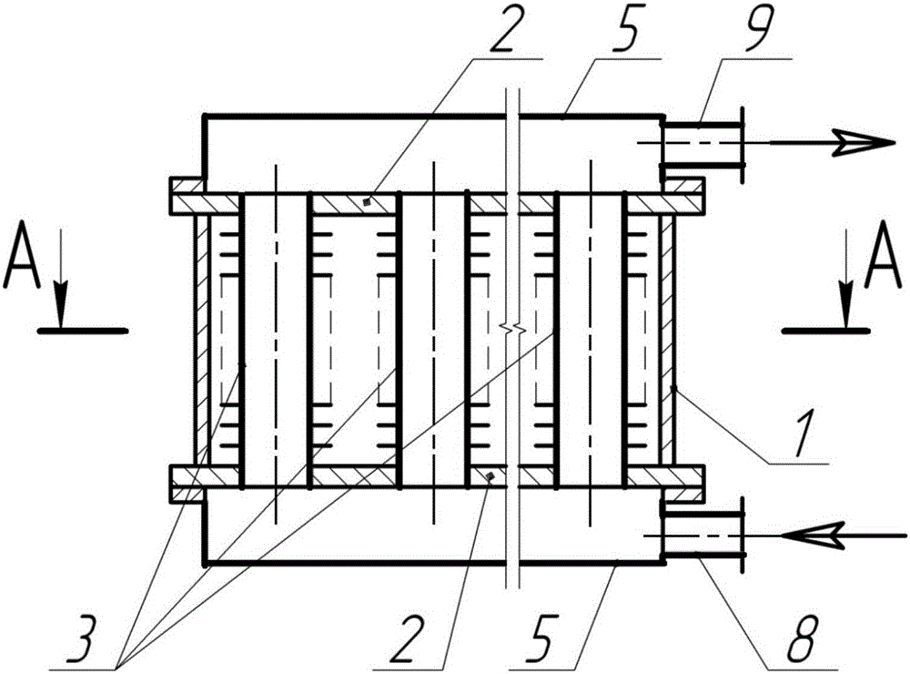
[0017] Embodiment 1, figure 1 , figure 2 Provided is an engine exhaust cooler, including a housing 1, the housing 1 has a built-in cavity, and the cavity is provided with a smoke flow channel and a coolant flow channel, and the smoke flow channel and the coolant flow channel are connected to each other. Intertwining, the flue gas temperature is cooled by cooling liquid.

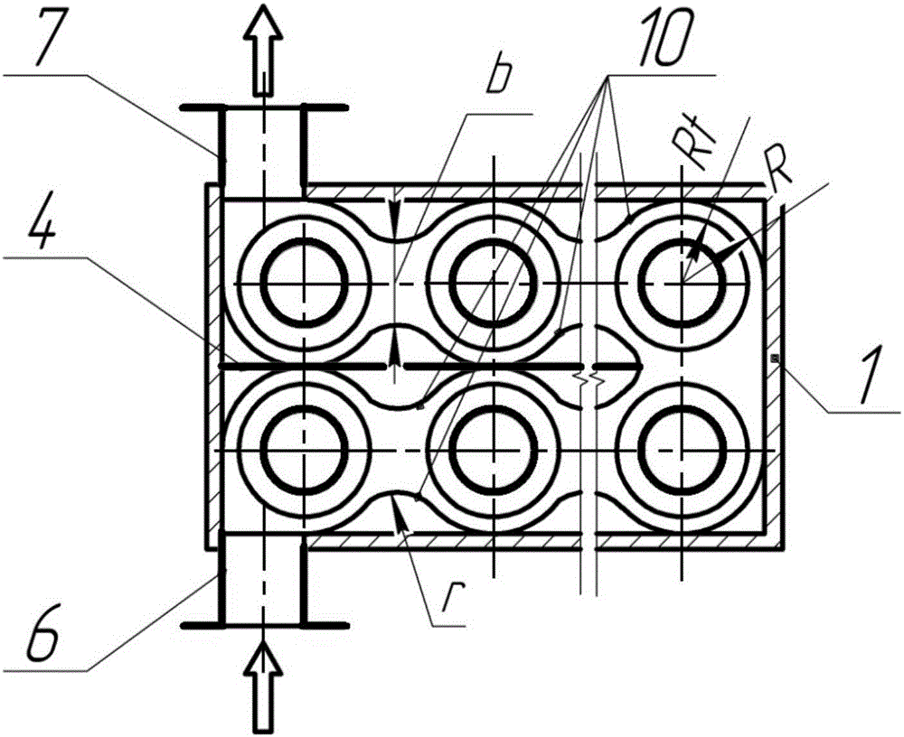
[0018] The flue gas flow channel is a deflector 10, and a partition 4 is vertically arranged on the bottom surface of the housing 1, and the deflector 10 is U-shaped by connecting two sections of circular arcs periodically along the direction of the partition 4. The U-shaped configuration enables the deflector 10 to achieve as long a travel space as possible in as small a space as possible, increasing the cooling effect.

[0019] And this cooling fluid channel is finned tube 3, and this finned tube 3 is inside deflector 10, realizes the supply function of cooling fluid by arranging water chamber housing 5 ...


PUM


Abstract

The invention discloses an engine exhaust cooler which comprises a shell (1), wherein the shell (1) is internally provided with a fume runner and a coolant runner which intersect with each other; the fume runner comprises guide plates (10); the coolant runner comprises finned tubes (3); the guide plates (10) are internally provided with the finned tubes (3); the finned tubes (3) and the guide plates (10) are correspondingly arranged so as to achieve an optimal cooling effect.

Description

technical field [0001] The invention relates to the technical field of gas coolers, especially the technical field of engine exhaust coolers. Background technique [0002] Due to the existence of tube bundles, the tube bundle gas cooler divides the interior of the cooler into different areas, resulting in different gas flow states in different areas, and thus different heat transfer intensities in different areas; when the gas to be cooled traverses the tube bundle, the exchange The heat transfer coefficient of the heat pipe circle varies greatly, and the maximum heat transfer coefficient in the area around the heat exchange tube is 2 to 3 times the minimum heat transfer coefficient. This uneven distribution of heat transfer coefficient seriously reduces the average heat exchange tube bundle. The heat transfer coefficient reduces the heat transfer power of the cooler. In order to achieve a certain cooling effect, the gas cooler needs to consume more materials, so the gas coo...

Claims


Application Information

Patent Timeline
Patent Type & Authority Applications(China)
IPC IPC(8): F01N3/04F28D7/16F28F9/22
CPCF01N3/043F28D7/1607F28F9/22F28F2009/222
Inventor 李其朋米哈洛·别兹罗德内宋德玉胥乐乐佩特罗·巴拉瓦什雅罗斯拉夫·托克兹德米特罗·库特罗
Owner ZHEJIANG UNIVERSITY OF SCIENCE AND TECHNOLOGY
Why Eureka
Try Eureka