
Distributed optical fiber-based transformer winding stress monitoring system

A technology of transformer winding and distributed optical fiber, which is applied in the direction of measurement, instrument, and measurement force by measuring the change of optical properties of materials when they are stressed, and can solve problems such as inability to demodulate signals, gaps, and calculation errors.

Inactive Publication Date: 2016-09-28
NORTH CHINA ELECTRIC POWER UNIV (BAODING)
View PDF6 Cites 10 Cited by
  • Summary
  • Abstract
  • Description
  • Claims
  • Application Information

AI Technical Summary

Problems solved by technology

[0003] At present, the domestic research on the axial and radial stress of transformer windings mainly adopts the theoretical calculation method, but due to the complex structure of the transformer, the calculation errors of related parameters such as current density, and the leakage flux of the winding as an elastic system is a coupling field under the impact force, There is still a large gap between the theoretical calculation results and the actual winding stress, which cannot provide support for the judgment of transformer winding deformation
At the same time, due to the intrusion wave of electromotive force generated on the winding and the short-circuit current has a high frequency, the existing demodulator cannot demodulate the signal, resulting in the difficulty that the analysis end cannot be synchronized with the detection end

Method used


Image

  • Distributed optical fiber-based transformer winding stress monitoring system
  • Distributed optical fiber-based transformer winding stress monitoring system
  • Distributed optical fiber-based transformer winding stress monitoring system

Examples


Embodiment Construction

[0016] The present invention will be described in detail below with reference to the accompanying drawings and in combination with embodiments.

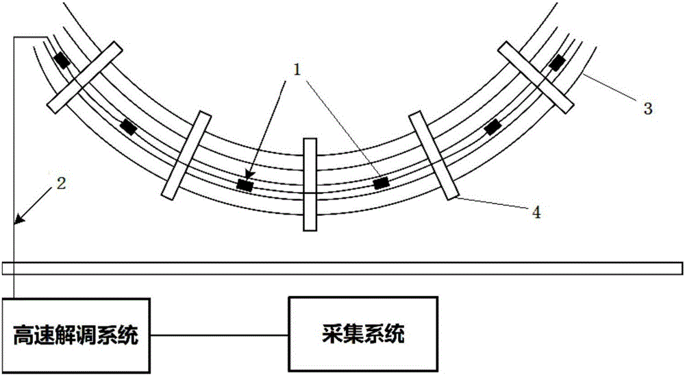
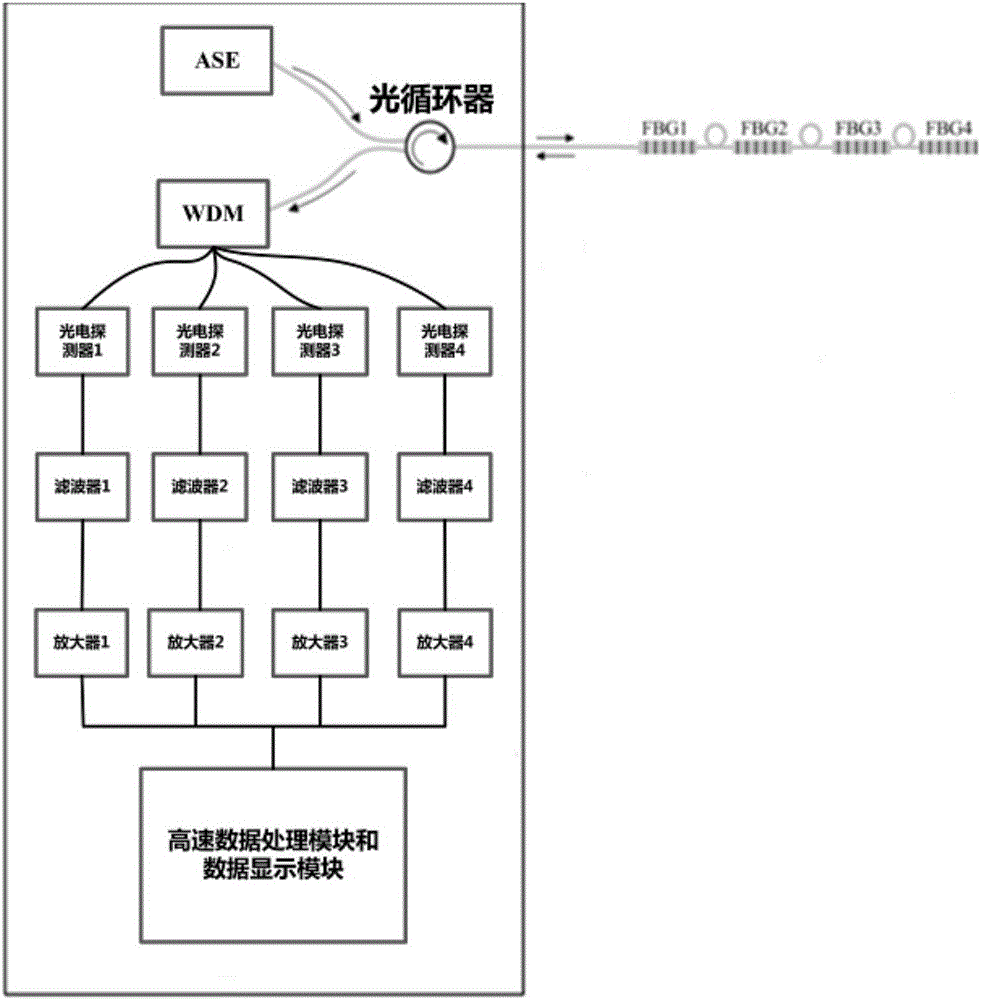
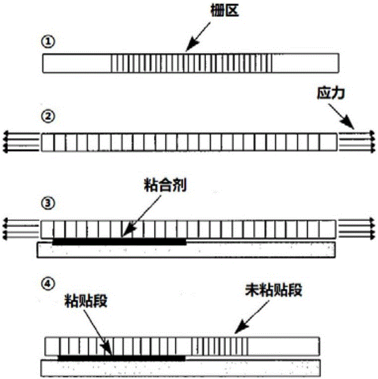
[0017] figure 1 A connection schematic diagram of a transformer winding stress monitoring system based on distributed optical fibers is shown. The optical fiber is packaged by partial pasting, and the fully distributed optical fiber stress sensor is pre-embedded in the winding magnet wire, and then the optical fiber is led out of the sensor and connected to the designed high-speed demodulation system, and the transformer winding stress is monitored in real time through the stress acquisition system. After the winding is affected by the impact force, the fully distributed optical fiber stress sensor embedded in the winding magnet wire is stressed, and the optical signals of different sensors are separated by the wavelength division multiplexing equipment in the high-speed demodulation system, and then the optical signal The conversio...


PUM


Abstract

The invention belongs to the on-line monitoring system technical field and relates to a distributed optical fiber-based transformer winding stress monitoring system. The distributed optical fiber-based transformer winding stress monitoring system is characterized in that a plurality of fully-distributed optical fiber stress sensors (1) are pre-embedded in electromagnetic wires of a high-voltage winding (3); the fully-distributed optical fiber stress sensors (1) are connected together by an optical fiber (2) and are fixed through clamping devices (4); the optical fiber (2) is led out from the fully-distributed optical fiber stress sensors (1) and is connected with a high-speed demodulation system; the output end of the high-speed demodulation system is connected with a stress acquisition system; and therefore, real-time monitoring of the stress of the transformer winding can be realized. With the distributed optical fiber-based transformer winding stress monitoring system adopted, rapid detection and distributed measurement of the stress of the winding can be realized; stress conditions at different positions of the winding can be mastered accurately under the effect of an impact force; the defect of low resolution of an existing demodulation instrument can be eliminated; and fast distributed monitoring of the electromotive force of the winding can be realized.

Description

technical field [0001] The invention belongs to the technical field of on-line monitoring systems, in particular to a transformer winding stress monitoring system based on distributed optical fibers. Background technique [0002] Power transformers are an important part of power systems. The transformer winding in operation will establish axial and radial leakage flux around it. When a short-circuit fault occurs or is impacted by lightning current, the large current flowing through the winding will cause the electromagnetic force on the winding to increase dramatically. After the winding is affected by the impact force, it will cause axial and radial dimension changes, winding distortion, bulging, etc., that is, winding deformation. The deformation of the winding may cause the insulation distance to change or the insulation paper to be damaged. When encountering lightning overvoltage, the transformer will break down between turns and cakes, and sudden damage accidents will ...

Claims


Application Information

Patent Timeline
Patent Type & Authority Applications(China)
IPC IPC(8): G01L1/24
CPCG01L1/246
Inventor 马国明吴震李成榕宋宏图刘姝嫔
Owner NORTH CHINA ELECTRIC POWER UNIV (BAODING)
Learn More