Automatic calorimeter for caloric analysis of sample

A calorimeter and calorific value technology, applied in the thermal development of materials, chemical instruments and methods, dissolution and other directions, can solve the problems of inconsistent oxygen bomb volume, affecting the test accuracy, affecting the constant volume accuracy, etc., to ensure the accuracy of test analysis, High precision of test analysis and guaranteed effect of constant volume

Active Publication Date: 2016-09-28
HUNAN SUNDY SCI & TECH DEV
View PDF13 Cites 3 Cited by
  • Summary
  • Abstract
  • Description
  • Claims
  • Application Information

AI Technical Summary

Problems solved by technology

[0004] 1. The stirring effect of the existing calorimeter is not good
Part of the inner barrel stirring device is placed on the top, and the inner barrel is stirred from the top, but this stirring method has strict requirements on the straightness of the shaft and affects the arrangement of the upper oxygen bomb; some calorimeters place the inner barrel stirring device on the bottom, but this The bottom needs to be rotated and sealed. The rotating seal is prone to water leakage. At the same time, due to the change of friction of the rotating sealing ring, the stirring effect is different, which affects the test accuracy; and the stirring blades at the bottom of some calorimeters are prone to deflection during high-speed stirring. Instability, which directly affects the uniform mixing requirements for the test water in the inner bucket, which makes the difference in the heat of the test water and also affects the test accuracy.
[0005] 2. The inner barrel of the existing calorimeter cannot be directly constant volume, or the volume constant is not accurate, which affects the test accuracy
The existing fixed-volume constant-vessel structure is relatively complex, and the instrument needs to design a large-volume constant-ves

Method used


Image

  • Automatic calorimeter for caloric analysis of sample
  • Automatic calorimeter for caloric analysis of sample
  • Automatic calorimeter for caloric analysis of sample

Examples


Embodiment Construction

[0034] The present invention will be described in further detail below in conjunction with specific embodiments and accompanying drawings.

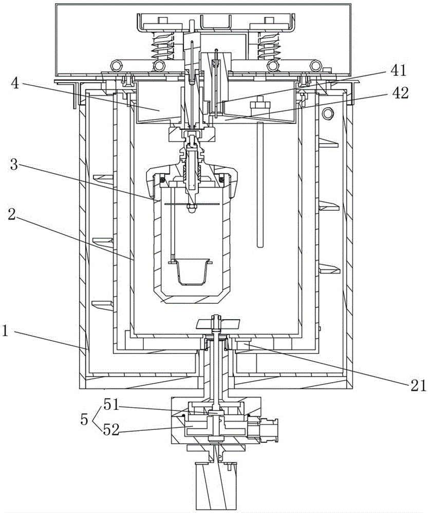
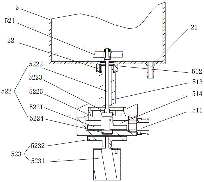
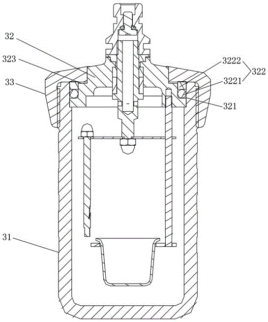
[0035] like Figure 1 to Figure 3 As shown, the present invention provides an automatic calorimeter for analyzing the calorific value of samples, comprising an outer barrel 1, an inner barrel 2, and an oxygen bomb 3, the oxygen bomb 3 is arranged in the inner barrel 2, and the inner barrel 2 is arranged in the outer barrel 1, The outer side of the outer barrel 1 is provided with a water supply stirring mechanism 5 for supplying and stirring water into the inner barrel 2. The water supply stirring mechanism 5 includes a water passage chamber 51 and a magnetic stirring assembly 52. ​​One end of the water passage chamber 51 is provided with a water inlet 511 for It communicates with external water supply equipment, and the other end of the water passage chamber 51 is provided with a water outlet 512 for communicating with the inner barrel 2 ...


PUM


Abstract

The invention discloses an automatic calorimeter for caloric analysis of a sample, comprising an outer barrel, an inner barrel and an oxygen bomb; the oxygen bomb is disposed in the inner barrel which is arranged in the outer barrel, a water supply stirring mechanism is arranged outside the outer barrel for supplying water to the inner barrel and stirring, the water supply stirring mechanism comprises a water supply chamber and a magnetic stirring assembly, one end of the water supply chamber is provided with a water inlet for communication with an external water supply apparatus, and the other end of the water supply chamber is provided with a water outlet for communicating with the inner barrel to supply water; the magnetic stirring assembly comprises stirring blades arranged in the inner barrel, a magnetic transmission part arranged in the water supply chamber and a magnetic drive part arranged outside the water supply chamber, the magnetic drive part cooperates with the magnetic transmission part to drive the magnetic transmission part to rotate, and the magnetic transmission part cooperates with the stirring blades to drive the stirring blades to move in sync for stirring. The calorimeter of the invention has the advantages of simple and compact structure, good stirring effect, high volume fixing precision and high test and analysis precision.

Description

technical field [0001] The invention mainly relates to the field of sample analysis instruments, in particular to an automatic calorimeter used for calorific value analysis of samples. Background technique [0002] For the laboratory analysis of material (such as ore, coal) samples, each country has mandatory standards, which must be followed. For example, taking the analysis of coal samples as an example, the principle of the sample analysis process is to conduct relevant analysis on the samples that meet the requirements without destroying the representativeness of the samples. The accuracy of the analysis, so that the test results can reflect the characteristics of the sample most truly. [0003] In the laboratory analysis of material (such as ore, coal) samples, it is often necessary to use a calorimeter to analyze the calorific value of the sample. Existing calorimeters often have the following technical problems: [0004] 1. The stirring effect of the existing calor...

Claims


Application Information

Patent Timeline
IPC IPC(8): G01N25/20B01F13/08
CPCG01N25/20B01F33/453B01F2101/23B01F33/45
Inventor 朱先德吴成乞胡亚军
Owner HUNAN SUNDY SCI & TECH DEV
Why Eureka
Try Eureka