
Continuous laser based detection method for ground layer aerosol backscattering coefficient profile

A technology of backscatter coefficient and detection method, which is applied in the detection field of backscatter coefficient profile, can solve problems such as restricting efficiency, difficulty in obtaining backscatter coefficient value, and limited detection range of backscatter lidar, so as to reduce The effect of reducing manufacturing cost and using cost

Active Publication Date: 2016-09-28
中国人民解放军陆军炮兵防空兵学院 +1
View PDF5 Cites 12 Cited by
  • Summary
  • Abstract
  • Description
  • Claims
  • Application Information

AI Technical Summary

Problems solved by technology

Although the method described in this invention patent can invert the profile of the aerosol backscatter coefficient, there are still some unsatisfactory points. First, the backscatter lidar or sounding balloon must be used to measure the The aerosol backscatter coefficient value at any point from 0.7 to 5km, especially in haze weather, the detection range of the backscatter lidar is limited, and the value of the aerosol backscatter coefficient at a height of 0.7 to 2km is obtained by other methods. Difficult, therefore, the existing methods that need to know the backscatter coefficient value of the reference point first, and then invert the aerosol backscatter coefficient profile are difficult to realize; secondly, the output power of the continuous laser needs to be greater than 10W; All of these have restricted its effectiveness in detecting the aerosol backscatter coefficient profile near the ground layer to varying degrees.

Method used


Image

  • Continuous laser based detection method for ground layer aerosol backscattering coefficient profile
  • Continuous laser based detection method for ground layer aerosol backscattering coefficient profile
  • Continuous laser based detection method for ground layer aerosol backscattering coefficient profile

Examples


Embodiment Construction

[0036] The preferred modes of the present invention will be further described in detail below in conjunction with the accompanying drawings.

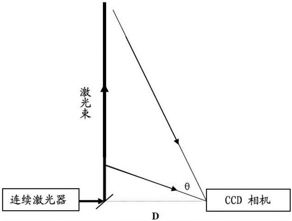
[0037] see figure 1 , The CCD lateral continuous laser radar is mainly composed of a continuous laser and a CCD camera. The CCD camera records the lateral scattered laser light of the continuous laser emission beam in the atmosphere. The side scattered light at different heights contains aerosol information at that height, and the intensity of side scattered light at different heights is recorded by different CCD pixels. By extracting and inverting the signal intensity on the pixel points in the CCD, the aerosol backscattering coefficient at different heights near the ground can be obtained.

[0038] When implementing the present invention, the parameter of continuous laser and CCD camera and relative position thereof are respectively, and the output wavelength of continuous laser is 532nm, power is 0.1~1W; The selection range of the t...


PUM


Abstract

The invention discloses a continuous laser based detection method for a ground layer aerosol backscattering coefficient profile. According to the invention, an arbitrary point at a height of 0.7 to 2 km is selected as a reference point and then scanning and value determining are performed on an empirical value of a backscattering coefficient within said height according to 1 / 80 to 1 / 1200 in (10<-4>-10<-1>)km<-1>sr<-1>, and 80-1200 defaults are obtained. Then, the 80-1200 defaults are substituted into a lateral scattering laser radar equation together with a signal measured by a continuous laser radar one by one for inversion of the backscattering coefficient profile, so that 80 to 1200 groups of profile data are obtained. Then backscattering coefficients at a height of 0-30m from the ground in the 80 to 1200 groups of profile data are compared with backscattering coefficients at the same height obtained by another device at the same location successively, and the aerosol backscattering coefficient profile is obtained based on a group of backscattering coefficient profile data containing values most approximate to values obtained by the other device. The method provided by the invention is easy to apply to detection of aerosol widely in the commercial field.

Description

technical field [0001] The invention relates to a detection method for a backscattering coefficient profile, in particular to a detection method for a near-surface aerosol backscattering coefficient profile based on a continuous laser. Background technique [0002] Lidar is a powerful tool to detect the backscatter coefficient of aerosol, mainly including backscatter lidar and side scatter lidar. At present, side scatter lidar is a new technology being studied internationally. It places the transmitter and receiver in two places. The receiver detects the side scattered light of the laser beam to retrieve the backward direction of the aerosol. Scattering coefficient, avoiding the influence of geometric factors in backscattering laser radar, high measurement accuracy at short distances, very suitable for measuring the spatial distribution of atmospheric aerosols near the ground, such as Chinese invention patent CN 103344611B in July 2015 The applicant's method for measuring a...

Claims


Application Information

Patent Timeline
Patent Type & Authority Applications(China)
IPC IPC(8): G01S17/95
CPCG01S17/95Y02A90/10
Inventor 陶宗明单会会张辉张清泽麻晓敏
Owner 中国人民解放军陆军炮兵防空兵学院
Learn More