Drying method of current transformer coil

A technology of current transformer and drying method, which is applied in the direction of coil manufacturing, drying solid materials, and combination of methods to dry solid materials, etc., can solve the problems of long drying time and high energy consumption, reduce drying time, improve product quality, and improve The effect of company capacity

Active Publication Date: 2016-09-28
HENAN PINGGAO ELECTRIC +3
View PDF6 Cites 2 Cited by
  • Summary
  • Abstract
  • Description
  • Claims
  • Application Information

AI Technical Summary

Problems solved by technology

[0005] The purpose of the invention is to provide a drying method for current transformer coils, thereby solving the problem of SF in the prior art 6 The drying of current transformer coils has the problems of long drying time and high energy consumption

Method used


Image

  • Drying method of current transformer coil

Examples


Embodiment 1

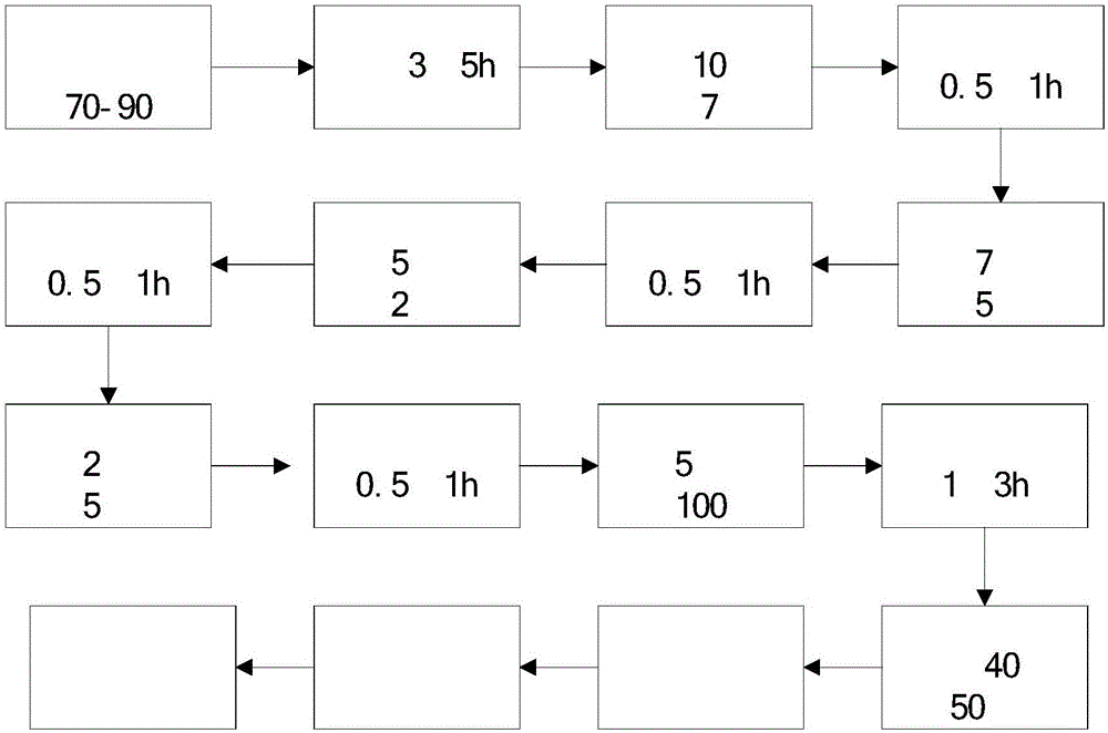
[0022] The drying method of the current transformer coil of the present embodiment, technological process is as follows figure 1 shown, including the following steps:

[0023] 1) Put the SF in the drying chamber 6 The current transformer coil is heated to 80°C and kept warm for 4 hours. During the heating and keeping warm process, the drying cavity is repeatedly pumped and inflated;

[0024] 2) Keep the temperature at 80°C, and vacuumize the drying chamber by gradient depressurization. First, vacuumize from normal pressure to 70kpa (0.25h), and keep the pressure for 1h; after keeping the pressure, fill it with dry air to 80kpa. Displace water vapor, then evacuate to 50kpa (time of 0.25h), hold pressure for 0.5h; after holding pressure, fill with dry air to 80kpa to replace water vapor, then evacuate to 20kpa (time of 0.25h), hold pressure for 0.5h ; After maintaining the pressure, fill it with dry air to 80kpa to replace the water vapor, then evacuate to 5ka (taking 0.25h), ...

Embodiment 2

[0027] The drying method of the current transformer coil of the present embodiment, technological process is as follows figure 1 shown, including the following steps:

[0028] 1) Put the SF in the drying chamber 6 Heat the coil of the current transformer to 70°C and keep it warm for 5 hours. During the process of heating and keeping warm, repeatedly pump and inflate the drying chamber;

[0029] 2) Keep the temperature at 70°C, and vacuumize the drying chamber by gradient depressurization. First, vacuumize from normal pressure to 70kpa (taking 0.25h), and keep the pressure for 1h; then evacuate from 70kpa to 50kpa (taking 0.25h ), hold the pressure for 1h; then vacuumize from 50kpa to 20kpa (0.25h), hold the pressure for 1h; then evacuate from 20kpa to 5ka (0.25h), hold the pressure for 1h; then evacuate from 5kpa to 100pa (use 1h ), the vacuum is maintained for 1h, and the pressure is released; in this process, the water vapor produced in the drying process is intermittently...

Embodiment 3

[0032] The drying method of the current transformer coil of the present embodiment, technological process is as follows figure 1 shown, including the following steps:

[0033] 1) Put the SF in the drying chamber 6 The current transformer coil is heated to 90°C and kept warm for 3 hours. During the heating and keeping warm process, the drying cavity is repeatedly pumped and inflated;

[0034]2) Keep the temperature at 90°C, and vacuumize the drying chamber by gradient step-down method. First, vacuumize from normal pressure to 70kpa (0.25h), and keep the pressure for 0.5h; then vacuumize from 70kpa to 50kpa (0.25h). h), hold the pressure for 0.5h; then vacuumize from 50kpa to 20kpa (0.25h), hold the pressure for 0.5h; then vacuumize from 20kpa to 5ka (use 0.25h), hold the pressure for 0.5h; then evacuate from 5kpa to 100pa (use time 1h), vacuum maintenance 2h; In this process, the water vapor produced in the drying process is intermittently replaced, and the specific operation...


PUM


Abstract

The invention discloses a drying method of a current transformer coil. The drying method comprises steps as follows: 1) the current transformer coil placed in a drying cavity is heated to 70-90 DEG C and subjected to thermal insulation; 2) the drying cavity is subjected to vacuum pumping at the temperature of 70-90 DEG C, and the pressure of the drying cavity is gradiently reduced until the vacuum degree is 100 pa or below; the temperature is reduced, and the current transformer coil is dried. By means of the drying method, moisture is basically kept below 50 ppm and is far lower than the international requirement of 150 ppm, the product quality is improved, the phenomenon that the coil is repeatedly dismounted and dried due to the fact that the moisture of the coil is out of limits is reduced, and the labor intensity of workers is reduced; the vacuum drying process of the coil lasts about 14 h, and compared with 48-60 h required for drying in a drying room, the drying time is greatly reduced; with the adoption of the production mode of blow-in drying at night and assembling in the daytime, the passive situation of waiting for drying of parts can be changed, the production cycle is shortened, and the productivity of a company is improved.

Description

technical field [0001] The invention belongs to the field of current transformers, in particular to a method for drying coils of current transformers. Background technique [0002] Current transformer is an important equipment for monitoring and measuring the operation of power equipment. It converts the high voltage and high current of the primary system into low voltage and small current in proportion, and supplies them to measuring instruments and protection devices. The current transformer is composed of a closed iron core, a primary coil wound on the core, a secondary coil and some installation parts. There is insulation isolation between the primary and secondary coils, and between the coil and the core. [0003] Current transformers are divided into dry insulation type, pouring insulation type, porcelain insulation type, oil insulation type and SF according to the insulation method. 6 Gas insulated. SF 6 The current transformer is one of the main components of the ...

Claims


Application Information

Patent Timeline
Patent Type & Authority Applications(China)
IPC IPC(8): H01F41/04F26B7/00
CPCF26B7/00H01F41/04
Inventor 张圣中陈东风田凤英陈晓瑞丁金庆
Owner HENAN PINGGAO ELECTRIC
Why Eureka
Try Eureka