Vibrating spear with modularized front-mounted power low-vibration vibrating head

A front-mounted power and vibrating head technology, which is applied to the processing of electromechanical devices, electric components, and building materials, can solve problems such as troublesome disassembly and maintenance, increased purchase costs, and operator injuries, so as to reduce manufacturing costs and shorten The effect of transmission distance and reduction of vibration intensity

Inactive Publication Date: 2016-09-28
ZHEJIANG ZILI CONSTR GRP
View PDF6 Cites 3 Cited by
  • Summary
  • Abstract
  • Description
  • Claims
  • Application Information

AI Technical Summary

Problems solved by technology

[0004] In the above structure, it is a motor rear-end driven structure. The steel cable 4' passes through the long leather sheath 2' and then reaches the vibrating head 3'. On the one hand, the long output distance requires a large motor 1' with high power. , the energy consumption is relatively large, and the rotation of the steel cable 4' will cause high-intensity vibrations to the long leather sheath 2', and the operator always grasps the long leather sheath at the rear of the vibrating head 3' for operation. The high-frequency vibration of the long leather case 2′ will cause great harm to the operator, and it will easily lead to the occurrence of occupational diseases of the arm vibration arm, seriously endangering the physical and mental health of the operator
[0005] In addition, the large motor 1', the long leather case 2' and the vibrating head 3' constituting the vibrating rod above are a solidly connected structure, which is not only cumbersome to disassemble and maintain, but the most important thing is that it is often necessary for different pouring scenarios in actual use The size of the vibrating head of different specifications requires the entire vibrating rod to be replaced, which not only increases the purchase cost, but also brings great inconvenience to the actual use

Method used


Image

  • Vibrating spear with modularized front-mounted power low-vibration vibrating head
  • Vibrating spear with modularized front-mounted power low-vibration vibrating head
  • Vibrating spear with modularized front-mounted power low-vibration vibrating head

Examples


Embodiment Construction

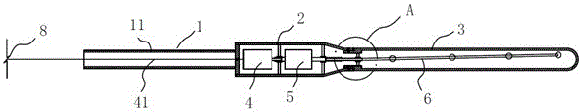
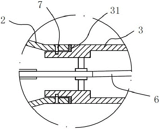
[0021] like figure 2 and 3 As shown, a modular vibrating rod with front power and low vibration vibrating head is composed of a hand-held part 1 , an intermediate body 2 and a vibrating head 3 connected in sequence. The handle 1 is covered with a leather sheath 11 for increasing the comfort of operation. The intermediate body 2 is provided with a driving small motor 4 and a speed change gear set 5, and the output shaft of the small motor 4 is connected with a steel cable 6 extending into the vibrating head through the speed change gear set 5.

[0022] The present invention breaks the drawbacks of the existing motor back-end drive, and it is a front-end drive structure of the motor. The small motor 4 is directly connected with the steel cable 6 in the vibrating head 3 through the speed change gear set 5 . This structural arrangement makes the entire transmission of the vibrating rod not need to pass through the hand-held part 1, which can effectively reduce the vibration int...


PUM


Abstract

The invention discloses a vibrating spear with a modularized front-mounted power low-vibration vibrating head. The whole vibrating spear is composed of a hand holding part, a middle body and a vibrating head connected in sequence, wherein the middle body is internally provided with a driving small motor and a change gear set; and the output shaft of the small motor is connected with a wire rope stretching into the vibrating head after passing through the change gear set. According to the vibrating spear, the vibration intensity of the hand holding part of the vibrating spear during operation can be effectively reduced, the bodily injury for workers is reduced, and the occurrence of vibrating arm occupational diseases is avoided; and moreover, the vibrating head is set to be of a modularized structure, different specifications of vibrating heads can be changed according to application scenarios, and the vibrating spear has the characteristic of simple and practical structure.

Description

technical field [0001] The invention relates to concrete pouring auxiliary equipment, in particular to a modular vibrating rod with a pre-powered low-vibration vibrating head. Background technique [0002] In the process of concrete pouring, a vibrating rod auxiliary device is used to improve the quality of pouring. In the operation, the high-frequency vibration generated by the vibrating rod is used to make the cement slurry dense, remove air bubbles, and eliminate the honeycomb surface of the concrete and other phenomena. , improve the strength of concrete pouring, and ensure the quality of concrete components. [0003] But at present, existing vibrator such as figure 1 As shown, it is mainly composed of a large motor 1' of 220V, a long leather case 2' and a vibrating head 3', wherein the output shaft of the motor 1' is connected with a steel cable 4' extending into the vibrating head 3'. When working, the high-frequency vibration of the vibrating head 3' is obtained by ...

Claims


Application Information

Patent Timeline
Patent Type & Authority Applications(China)
IPC IPC(8): H02K7/116H02K7/14E04G21/08
CPCH02K7/116E04G21/08H02K7/145
Inventor 叶国兵黄俊朱仁贵陈启照黄月婷顾士理
Owner ZHEJIANG ZILI CONSTR GRP
Why Eureka
Try Eureka