3C electronic product shell and manufacturing method thereof

A technology for electronic products and casings, which is applied in the field of 3C electronic product casings and its preparation, and can solve the problems that structural parts cannot maintain a complete and coherent appearance effect, cannot meet high-end fashion appearance effects, and reduce the metal texture experience effect of casings, etc. , to meet the requirements of appearance quality, improve the problem of easy cracking, and facilitate mass production

Inactive Publication Date: 2016-09-28
GUANGDONG JANUS SMART GRP CO LTD
View PDF8 Cites 18 Cited by
  • Summary
  • Abstract
  • Description
  • Claims
  • Application Information

AI Technical Summary

Problems solved by technology

[0003] Although the use of metal materials can improve the strength and texture of the electronic product shell, due to the shielding of the antenna signal of the communication electronic product, it is necessary to process the antenna on the metal part and use plastic connection to solve the signal problem of the communication electronic product. Structural parts Cannot maintain a complete and coherent appearance
[0004] At the same time, due to the limitations of traditional processing methods, equipment, materials and costs, the width of the cutting position of the metal shell antenna of communication electronic products is more than 1.2mm, so that the filled plastic material leaks out on the appearance of the metal shell, and consumers can It is obvious that there is a significant difference in feel from metal materials, which greatly reduces the metal texture of the shell and the experience effect of consumers. It cannot satisfy the high-end and fashionable appearance effect but is difficult to eliminate

Method used


Image

  • 3C electronic product shell and manufacturing method thereof
  • 3C electronic product shell and manufacturing method thereof
  • 3C electronic product shell and manufacturing method thereof

Examples


Embodiment Construction

[0040] Embodiments of the present invention will be described in detail below. It should be emphasized that the following description is only exemplary and not intended to limit the scope of the invention and its application.

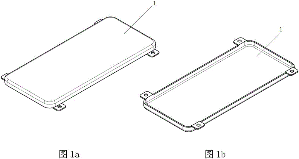
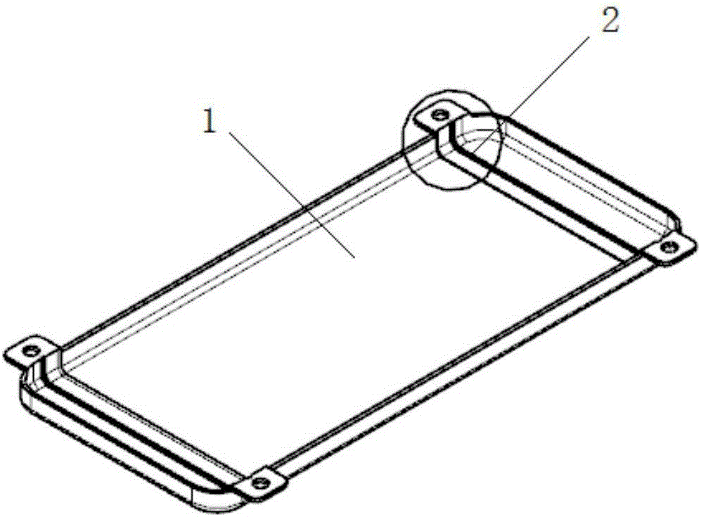
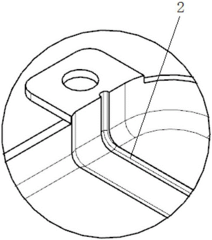
[0041] refer to Figure 1a to Figure 8c , in one embodiment, a 3C electronic product housing, including a metal structure 1 as the shell body, an antenna slot is opened between the back and the front of the metal structure 1, and the antenna slot includes a slot The cavity 2 and the antenna slitting micro-slit 3 penetrating from the cavity 2 to the front of the metal structure 1, the antenna slitting micro-slit 3 is filled with a non-conductive substance, and the metal structure 1 There is an integrally injection-molded plastic structure layer 4 on the back side, and the plastic structure layer 4 at least partially fills the slot cavity 2 of the antenna slot.

[0042] The specific width and quantity of the micro-slits for cutting the antenna can be de...


PUM


Abstract

The invention discloses a 3C electronic product shell and a manufacturing method thereof. The 3C electronic product shell comprises a metallic structure, an antenna slot penetrates through the back and the front of the metallic structure, the antenna slot comprises a slot cavity and an antenna cutting position slit penetrating through the front of the metallic structure from the slot cavity, the antenna cutting position slit is filled with a nonconductive matter, an integrally inject-molded plastic structure layer is arranged on the back of the metallic structure, and the slot cavity is filled with at least part of the plastic structure layer. The 3C electronic product shell is favorable for completely solving the problem that the antenna cutting position on the surface of the electronic product metal shell is exposed, so that the electronic product metal shell is coherent in overall appearance and strong in metallic texture; and the 3C electronic product shell is simple in manufacturing process, low in cost and suitable for large-scale production, meets the requirement of 3C electronic product structures for appearance quality, and simultaneously has the advantages of easiness in manufacturing, low cost and practicability.

Description

technical field [0001] The invention relates to a 3C electronic product casing and a preparation method thereof. Background technique [0002] With the development needs of 3C (Computer, Communication, Consumer Electronics, computer, communication and consumer electronics) electronic products for miniaturization, thinning, fashion and practicality, more and more shells of existing electronic products are made of light weight and High-strength metal materials, such as aluminum alloy, stainless steel, titanium alloy, etc., to meet the needs of thinner and thinner products, higher and higher strength of the whole machine, light weight, outstanding texture and fast heat dissipation. [0003] Although the use of metal materials can improve the strength and texture of the electronic product shell, due to the shielding of the antenna signal of the communication electronic product, it is necessary to process the antenna on the metal part and use plastic connection to solve the signa...

Claims


Application Information

Patent Timeline
Patent Type & Authority Applications(China)
IPC IPC(8): H05K5/04H05K5/02
CPCH05K5/04H05K5/0247
Inventor 唐臻谢守德王长明
Owner GUANGDONG JANUS SMART GRP CO LTD
Why Eureka
Try Eureka